# PBS Library Network
Projects 3 / 5
17 min read
Table of Contents
Project Overview
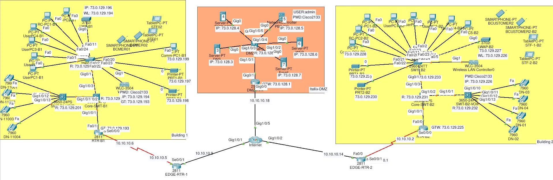
This project implements a comprehensive enterprise network infrastructure for the PBS (Public Broadcasting Service) Library across multiple buildings. The network design includes VLANs, routing, VoIP services, security policies, and a DMZ for public-facing services.
Network Architecture
The network consists of three main segments:
Building 1 (B1)
- Router: RTR-B1
- Core Switch: CORE-SWT-B1
- Access Switch: SW1_B1
- VoIP Switch: SWT-B1-VOIP
Building 2 (B2)
- Router: RTR-B2
- Core Switch: CORE-SWT-B2
- Access Switch: SW1_B2
- VoIP Switch: SWT-B2-VOIP
DMZ (Demilitarized Zone)
- Router: DMZ-RTR
- Switch: DMZ-SWT
Network Configuration
IP Addressing and Subnetting
| VLAN | Name | Needed hosts | CIDR | Subnet Mask | Wildcard Mask | Network ID | Usable range | Broadcast || ---- | ------------------- | -----------: | :--- | --------------- | ------------- | --------------- | --------------------------- | ------------ || 300 | DMZ | 254 | /24 | 255.255.255.0 | 0.0.0.255 | 73.0.128.0/24 | 73.0.128.1 – 73.0.128.254 | 73.0.128.255 || 214 | BYOD Customers (B2) | 63 | /25 | 255.255.255.128 | 0.0.0.127 | 73.0.129.0/25 | 73.0.129.1 – 73.0.129.126 | 73.0.129.127 || 114 | BYOD Customers (B1) | 51 | /26 | 255.255.255.192 | 0.0.0.63 | 73.0.129.128/26 | 73.0.129.129 – 73.0.129.190 | 73.0.129.191 || 115 | Management (B1) | 30 | /27 | 255.255.255.224 | 0.0.0.31 | 73.0.129.192/27 | 73.0.129.193 – 73.0.129.222 | 73.0.129.223 || 215 | Management (B2) | 27 | /27 | 255.255.255.224 | 0.0.0.31 | 73.0.129.224/27 | 73.0.129.225 – 73.0.129.254 | 73.0.129.255 || 111 | Customers (B1) | 16 | /27 | 255.255.255.224 | 0.0.0.31 | 73.0.130.0/27 | 73.0.130.1 – 73.0.130.30 | 73.0.130.31 || 211 | Customers (B2) | 16 | /27 | 255.255.255.224 | 0.0.0.31 | 73.0.130.32/27 | 73.0.130.33 – 73.0.130.62 | 73.0.130.63 || 113 | BYOD Staff (B1) | 22 | /27 | 255.255.255.224 | 0.0.0.31 | 73.0.130.64/27 | 73.0.130.65 – 73.0.130.94 | 73.0.130.95 || 213 | BYOD Staff (B2) | 22 | /27 | 255.255.255.224 | 0.0.0.31 | 73.0.130.96/27 | 73.0.130.97 – 73.0.130.126 | 73.0.130.127 || 112 | Reception (B1) | 8 | /28 | 255.255.255.240 | 0.0.0.15 | 73.0.130.128/28 | 73.0.130.129 – 73.0.130.142 | 73.0.130.143 || 116 | VOIP (B1) | 8 | /28 | 255.255.255.240 | 0.0.0.15 | 73.0.130.144/28 | 73.0.130.145 – 73.0.130.158 | 73.0.130.159 || 212 | Reception (B2) | 8 | /28 | 255.255.255.240 | 0.0.0.15 | 73.0.130.160/28 | 73.0.130.161 – 73.0.130.174 | 73.0.130.175 || 216 | VOIP (B2) | 8 | /28 | 255.255.255.240 | 0.0.0.15 | 73.0.130.176/28 | 73.0.130.177 – 73.0.130.190 | 73.0.130.191 |Building 1 Configuration
Core Switch Configuration
!VLAN 116 - VOIP 73.0.130.144/(255.255.255.240)28!VLAN 115 - MANAGEMENT 73.0.129.192/(255.255.255.224)27!VLAN 114 - BOYD-CUSTOMERS 73.0.129.128/(255.255.255.192)26!VLAN 113 - BOYD-STAFF 73.0.130.64/(255.255.255.224)27!VLAN 112 - RECEPTION  73.0.130.128/(255.255.255.240)28!VLAN 111 - CUSTOMERS 73.0.130.0/(255.255.255.224)27
!CORE-SWT-B1
enable
conf terminal
hostname CORE-SWT-B1
no ip domain-lookup
vlan 116    name VOIP    exit
vlan 115    name MANAGEMENT    exit
vlan 114    name BOYD-CUSTOMERS    exit
vlan 113    name BOYD-STAFF    exit
vlan 112    name RECEPTION    exit
vlan 111    name CUSTOMERS    exit
 interf range g1/0/1-3  switchport mode trunk  switchport trunk native vlan 115  switchport trunk allow vlan 116,113,114,111,112,115  exit
interf vlan 115    desc ip for remote MANAGEMENT    ip add 73.0.129.200 255.255.255.224    no shutdown    exit
interf range g1/0/4-24,g1/1/1-4    switchport mode access    switchport access vlan 115    shutdown    exit
Router Configuration
!VLAN-114 - BOYD-CUSTOMERS 73.0.129.128/(255.255.255.192)26!VLAN-115 - MANAGEMENT 73.0.129.192/(255.255.255.224)27!VLAN-113 - BOYD-STAFF 73.0.130.64/(255.255.255.224)27!VLAN-111 - CUSTOMERS 73.0.130.0/(255.255.255.224)27!VLAN-112 - RECEPTION  73.0.130.128/(255.255.255.240)28!VLAN-116 - VOIP 73.0.130.144/(255.255.255.240)28

!RTR-B1
enable
conf terminal
hostname RTR-B1
no ip domain-lookup
interf f0/1  no shutdown  exit
interf f0/1.114  description GWT: VLAN 114  encaps dot1q 114  ip add 73.0.129.129 255.255.255.192  exit
interf f0/1.115  description GWT: VLAN 115  encaps dot1q 115 native  ip add 73.0.129.193 255.255.255.224  exit
interf f0/1.113  description GWT: VLAN 113  encaps dot1q 113  ip add 73.0.130.65 255.255.255.224  exit
interf f0/1.111  description GWT: VLAN 111  encaps dot1q 111  ip add 73.0.130.1 255.255.255.224  exit

interf f0/1.112  description GWT: VLAN 112  encaps dot1q 112  ip add 73.0.130.129 255.255.255.240  exit
interf f0/1.116  description GWT: VLAN 116  encaps dot1q 116  ip add 73.0.130.145 255.255.255.240  exit

ip dhcp excluded-address 73.0.129.129 73.0.129.131ip dhcp pool VLAN114    network  73.0.129.128 255.255.255.192    dns-server 73.0.128.3    default-router 73.0.129.129    exit

ip dhcp excluded-address 73.0.130.65  73.0.130.67ip dhcp pool VLAN113    network 73.0.130.64 255.255.255.224    dns-server 73.0.128.3    default-router 73.0.130.65    exit
ip dhcp excluded-address 73.0.130.129ip dhcp pool VLAN112    network 73.0.130.128 255.255.255.240    dns-server 73.0.128.3    default-router 73.0.130.129    exit

ip dhcp excluded-address 73.0.130.1ip dhcp pool VLAN111    network 73.0.130.0 255.255.255.224    dns-server 73.0.128.3    default-router 73.0.130.1    exit

ip dhcp excluded-address 73.0.130.145ip dhcp pool VLAN116    network 73.0.130.144 255.255.255.240    default-router 73.0.130.145    option 150 ip 73.0.130.145    exit
telephony-service    max-ephone 4    max-dn 4    ip source-address 73.0.130.145 port 2000    auto assign 1 to 4    exit
ephone-dn 1    number 11001    exit
ephone-dn 2    number 11002    exit
ephone-dn 3    number 11003    exit
ephone-dn 4    number 11004    exit
dial-peer voice 1 voip    destination-pattern 2200.    session target ipv4:10.10.10.2    exit
router ospf 1    network 73.0.129.128 0.0.0.63 area 0    network 73.0.129.192 0.0.0.31 area 0    network 73.0.130.64 0.0.0.31 area 0    network 73.0.130.0 0.0.0.31 area 0    network 73.0.130.128 0.0.0.15 area 0    network 73.0.130.144 0.0.0.15 area 0    network 10.10.10.4 0.0.0.3 area 0    passive-interf f0/1.114    passive-interf f0/1.115    passive-interf f0/1.113    passive-interf f0/1.111    passive-interf f0/1.112    passive-interf f0/1.116    exit
!Secuirty
banner motd #      .-"      "-.     /            \    |,  .-.  .-.  ,|    | )(_o/  \o_)( |    |/     /\     \|    (_     ^^     _)     \__|IIIIII|__/      | \IIIIII/ |      \          /       `--------`
!!!  Unauthorized Access is Forbidden !!!#
enable secret admin
! Configuration of Console Mode/User Modeline console 0logging synchronousexec-timeout 6password adminloginexit
!Initial Configuration for a Secure Remote Accessusername intern privilege 1 password adminusername admin privilege 15 secret admin
crypto key generate rsaip domain-name library.com.aucrypto key generate rsa general-keys modulus 1024ip ssh version 2
line vty 0 4logging synchronousexec-timeout 5 30login localtransport input sshexit
service password-encryption
!VLAN 115 to all VLAN to the B1(VLAN214,VLAN215,VLAN213,VLAN211,VLAN212,VLAN216)!Access List Creation

ip access-list extended B1toB2 remark VLAN 115 to All VLAN on the B2 permit ip 73.0.129.192 0.0.0.31 73.0.129.0 0.0.0.127 permit ip 73.0.129.192 0.0.0.31 73.0.129.224 0.0.0.31 permit ip 73.0.129.192 0.0.0.31 73.0.130.96 0.0.0.31 permit ip 73.0.129.192 0.0.0.31 73.0.130.32 0.0.0.31 permit ip 73.0.129.192 0.0.0.31 73.0.130.160 0.0.0.15 permit ip 73.0.129.192 0.0.0.31 73.0.130.176 0.0.0.15 exit
ip access-list extended B1toB2 remark VLAN 114 to All VLAN on the B2 permit ip 73.0.129.128 0.0.0.63 73.0.129.0 0.0.0.127 permit ip 73.0.129.128 0.0.0.63 73.0.129.224 0.0.0.31 permit ip 73.0.129.128 0.0.0.63 73.0.130.96 0.0.0.31 permit ip 73.0.129.128 0.0.0.63 73.0.130.32 0.0.0.31 permit ip 73.0.129.128 0.0.0.63 73.0.130.160 0.0.0.15 permit ip 73.0.129.128 0.0.0.63 73.0.130.176 0.0.0.15 exit
 ip access-list extended B1toB2 remark VLAN 113 to All VLAN on the B2 permit ip 73.0.130.64 0.0.0.31 73.0.129.0 0.0.0.127 permit ip 73.0.130.64 0.0.0.31 73.0.129.224 0.0.0.31 permit ip 73.0.130.64 0.0.0.31 73.0.130.96 0.0.0.31 permit ip 73.0.130.64 0.0.0.31 73.0.130.32 0.0.0.31 permit ip 73.0.130.64 0.0.0.31 73.0.130.160 0.0.0.15 permit ip 73.0.130.64 0.0.0.31 73.0.130.176 0.0.0.15 exit
 ip access-list extended B1toB2 remark VLAN 111 to All VLAN on the B2 permit ip 73.0.130.0 0.0.0.31 73.0.129.0 0.0.0.127 permit ip 73.0.130.0 0.0.0.31 73.0.129.224 0.0.0.31 permit ip 73.0.130.0 0.0.0.31 73.0.130.96 0.0.0.31 permit ip 73.0.130.0 0.0.0.31 73.0.130.32 0.0.0.31 permit ip 73.0.130.0 0.0.0.31 73.0.130.160 0.0.0.15 permit ip 73.0.130.0 0.0.0.31 73.0.130.176 0.0.0.15 exit
 ip access-list extended B1toB2 remark VLAN 112 to All VLAN on the B2 permit ip 73.0.130.128 0.0.0.15 73.0.129.0 0.0.0.127 permit ip 73.0.130.128 0.0.0.15 73.0.129.224 0.0.0.31 permit ip 73.0.130.128 0.0.0.15 73.0.130.96 0.0.0.31 permit ip 73.0.130.128 0.0.0.15 73.0.130.32 0.0.0.31 permit ip 73.0.130.128 0.0.0.15 73.0.130.160 0.0.0.15 permit ip 73.0.130.128 0.0.0.15 73.0.130.176 0.0.0.15 exit
 ip access-list extended B1toB2 remark VLAN 116 to All VLAN on the B2 permit ip 73.0.130.144 0.0.0.15 73.0.129.0 0.0.0.127 permit ip 73.0.130.144 0.0.0.15 73.0.129.224 0.0.0.31 permit ip 73.0.130.144 0.0.0.15 73.0.130.96 0.0.0.31 permit ip 73.0.130.144 0.0.0.15 73.0.130.32 0.0.0.31 permit ip 73.0.130.144 0.0.0.15 73.0.130.160 0.0.0.15 permit ip 73.0.130.144 0.0.0.15 73.0.130.176 0.0.0.15 exit
ip access-list extended B1toDMZ remark VLAN All VLAN to DMZ permit ip 73.0.129.192 0.0.0.31 73.0.128.0 0.0.0.255 permit ip 73.0.129.128 0.0.0.63 73.0.128.0 0.0.0.255 permit ip 73.0.130.64 0.0.0.31 73.0.128.0 0.0.0.255 permit ip 73.0.130.0 0.0.0.31 73.0.128.0 0.0.0.255 permit ip 73.0.130.128 0.0.0.15 73.0.128.0 0.0.0.255 permit ip 73.0.130.144 0.0.0.15 73.0.128.0 0.0.0.255 exit
ip access-list extended BLOCK_FACEBOOK remark Block Facebook (lab server at 10.10.10.26) deny ip any host 10.10.10.26 exit

interface s0/0/0 crypto map VPN-MAP-LAB exit
!to check the vpn encryptionsh crypto ipsec sa
Access Switch Configuration
!VLAN 115 - MANAGEMENT 73.0.129.192/(255.255.255.224)27!VLAN 114 - BOYD-CUSTOMERS 73.0.129.128/(255.255.255.192)26!VLAN 113 - BOYD-STAFF 73.0.130.64/(255.255.255.224)27!VLAN 112 - RECEPTION  73.0.130.128/(255.255.255.240)28!VLAN 111 - CUSTOMERS 73.0.130.0/(255.255.255.224)27
!SW1_B1
enable
conf terminal
hostname SW1_B1
no ip domain-lookup

vlan 115    name MANAGEMENT    exit
vlan 114    name BOYD-CUSTOMERS    exit
vlan 113    name BOYD-STAFF    exit
vlan 112    name RECEPTION    exit
vlan 111    name CUSTOMERS    exit
 interf range g0/1,f0/23-24  switchport mode trunk  switchport trunk native vlan 115  switchport trunk allow vlan 113,114,111,112,115  exit
interf range f0/1-4  switchport mode access  switchport access vlan 111  exit
interf range f0/20-22  switchport mode access  switchport access vlan 115  exit
interf range f0/10-11  switchport mode access  switchport access vlan 112  exit

interf range f0/5-9,f0/12-19,g0/2    switchport mode access    switchport access vlan 115    shutdown    exit
interf vlan 115    desc ip for remote MANAGEMENT    ip add 73.0.129.202 255.255.255.224    no shutdown    exit
!Secuirty
banner motd #      .-"      "-.     /            \    |,  .-.  .-.  ,|    | )(_o/  \o_)( |    |/     /\     \|    (_     ^^     _)     \__|IIIIII|__/      | \IIIIII/ |      \          /       `--------`
!!!  Unauthorized Access is Forbidden !!!#
enable secret admin
! Configuration of Console Mode/User Modeline console 0logging synchronousexec-timeout 6password adminloginexit
!Initial Configuration for a Secure Remote Accessusername intern privilege 1 password adminusername admin privilege 15 secret admin
crypto key generate rsaip domain-name library.com.aucrypto key generate rsa general-keys modulus 1024ip ssh version 2
line vty 0 4logging synchronousexec-timeout 5 30login localtransport input sshexit
service password-encryption
interf range f0/1-4,f0/10-11  switchport port-security  switchport port-security mac-add stick  switchport port-security maximum 4  switchport port-security violation shutdown  exit
VoIP Switch Configuration
!VLAN 116 - VOIP 73.0.130.144/(255.255.255.240)28!VLAN 115 - MANAGEMENT 73.0.129.192/(255.255.255.224)27
!SWT-B1-VOIP
enable
conf terminal
hostname SWT-B1-VOIP
no ip domain-lookup
vlan 116    name VOIP    exit
vlan 115    name MANAGEMENT    exit

 interf g1/0/1  switchport mode trunk  switchport trunk native vlan 115  switchport trunk allow vlan 116,115  exit

interf range g1/0/10-13    switchport mode access    switchport voice vlan 116    exit
interf range g1/0/2-9,g1/0/14-24,g1/1/1-4    switchport mode access    switchport access vlan 115    shutdown    exit
interf vlan 115    desc ip for remote MANAGEMENT    ip add 73.0.129.20 255.255.255.224    no shutdown    exit

!Secuirty
banner motd #      .-"      "-.     /            \    |,  .-.  .-.  ,|    | )(_o/  \o_)( |    |/     /\     \|    (_     ^^     _)     \__|IIIIII|__/      | \IIIIII/ |      \          /       `--------`
!!!  Unauthorized Access is Forbidden !!!#
enable secret admin
! Configuration of Console Mode/User Modeline console 0logging synchronousexec-timeout 6password adminloginexit
!Initial Configuration for a Secure Remote Accessusername intern privilege 1 password adminusername admin privilege 15 secret admin
crypto key generate rsaip domain-name library.com.aucrypto key generate rsa general-keys modulus 1024ip ssh version 2
line vty 0 4logging synchronousexec-timeout 5 30login localtransport input sshexit
service password-encryption
interf range g1/0/10-13  switchport port-security  switchport port-security mac-add stick  switchport port-security maximum 4  switchport port-security violation shutdown  exit
Building 2 Configuration
Core Switch Configuration
!VLAN-214 - BOYD-CUSTOMERS 73.0.129.0/(255.255.255.128)25!VLAN-215 - MANAGEMENT 73.0.129.224/(255.255.255.224)27!VLAN-213 - BOYD-STAFF 73.0.130.96/(255.255.255.224)27!VLAN-211 - CUSTOMERS 73.0.130.32/(255.255.255.224)27!VLAN-212 - RECEPTION 73.0.130.160/(255.255.255.240)28!VLAN-216 - VOIP 73.0.130.176/(255.255.255.240)28
!CORE-SWT-B1
enable
conf terminal
hostname CORE-SWT-B2
no ip domain-lookup
vlan 216    name VOIP    exit
vlan 215    name MANAGEMENT    exit
vlan 214    name BOYD-CUSTOMERS    exit
vlan 213    name BOYD-STAFF    exit
vlan 212    name RECEPTION    exit
vlan 211    name CUSTOMERS    exit
 interf range g1/0/1-3  switchport mode trunk  switchport trunk native vlan 215  switchport trunk allow vlan 216,214,213,212,211,215  exit
interf vlan 215    desc ip for remote MANAGEMENT    ip add 73.0.129.231 255.255.255.224    no shutdown    exit
interf range g1/0/4-24,g1/1/1-4    switchport mode access    switchport access vlan 215    shutdown    exit
ip default-gateway 73.0.129.225
Router Configuration
!VLAN-214 - BOYD-CUSTOMERS 73.0.129.0/(255.255.255.128)25!VLAN-215 - MANAGEMENT 73.0.129.224/(255.255.255.224)27!VLAN-213 - BOYD-STAFF 73.0.130.96/(255.255.255.224)27!VLAN-211 - CUSTOMERS 73.0.130.32/(255.255.255.224)27!VLAN-212 - RECEPTION 73.0.130.160/(255.255.255.240)28!VLAN-216 - VOIP 73.0.130.176/(255.255.255.240)28
!RTR-B2
enable
conf terminal
hostname RTR-B2
no ip domain-lookup
interf f0/0  no shutdown  exit
interf f0/0.214  description GWT: VLAN 214  encaps dot1q 214  ip add 73.0.129.1 255.255.255.128  exit
interf f0/0.215  description GWT: VLAN 215  encaps dot1q 215 native  ip add 73.0.129.225 255.255.255.224  exit
interf f0/0.213  description GWT: VLAN 213  encaps dot1q 213  ip add 73.0.130.97 255.255.255.224  exit
interf f0/0.211  description GWT: VLAN 211  encaps dot1q 211  ip add 73.0.130.33 255.255.255.224  exit

interf f0/0.212  description GWT: VLAN 212  encaps dot1q 212  ip add 73.0.130.161 255.255.255.240  exit
interf f0/0.216  description GWT: VLAN 216  encaps dot1q 216  ip add 73.0.130.177 255.255.255.240  exit

ip dhcp excluded-address 73.0.129.1  73.0.129.3ip dhcp pool VLAN214    network 73.0.129.0 255.255.255.128    dns-server 73.0.128.3    default-router 73.0.129.1    exit

ip dhcp excluded-address 73.0.130.97 73.0.130.99ip dhcp pool VLAN213    network 73.0.130.96  255.255.255.224    dns-server 73.0.128.3    default-router 73.0.130.97    exit
ip dhcp excluded-address 73.0.130.33ip dhcp pool VLAN211    network 73.0.130.32 255.255.255.224    dns-server 73.0.128.3    default-router 73.0.130.33    exit

ip dhcp excluded-address 73.0.130.161ip dhcp pool VLAN212    network 73.0.130.160 255.255.255.240    dns-server 73.0.128.3    default-router 73.0.130.161    exit

ip dhcp excluded-address 73.0.130.177ip dhcp pool VLAN216    network 73.0.130.176 255.255.255.240    default-router 73.0.130.177    option 150 ip 73.0.130.177    exit
telephony-service    max-ephone 4    max-dn 4    ip source-address 73.0.130.177 port 2000    auto assign 1 to 4    exit
ephone-dn 1    number 22001    exit
ephone-dn 2    number 22002    exit
ephone-dn 3    number 22003    exit
ephone-dn 4    number 22004    exit
dial-peer voice 1 voip    destination-pattern 1100.    session target ipv4:10.10.10.6    exit
router ospf 1    network 73.0.129.0 0.0.0.127 area 0    network 73.0.129.224 0.0.0.31 area 0    network 73.0.130.96 0.0.0.31 area 0    network 73.0.130.32 0.0.0.31 area 0    network 73.0.130.160 0.0.0.15 area 0    network 73.0.130.176 0.0.0.15 area 0    passive-interf f0/0.214    passive-interf f0/0.215    passive-interf f0/0.213    passive-interf f0/0.211    passive-interf f0/0.212    passive-interf f0/0.216    exit
ip access-list extended B2toB1 remark VLAN 215 to All VLAN on the B1 permit ip 73.0.129.224 0.0.0.31 73.0.129.192 0.0.0.31 permit ip 73.0.129.224 0.0.0.31 73.0.129.128 0.0.0.63 permit ip 73.0.129.224 0.0.0.31 73.0.130.64 0.0.0.31 permit ip 73.0.129.224 0.0.0.31 73.0.130.0 0.0.0.31 permit ip 73.0.129.224 0.0.0.31 73.0.130.128 0.0.0.15 permit ip 73.0.129.224 0.0.0.31 73.0.130.144 0.0.0.15 exit
ip access-list extended B2toB1 remark VLAN 214 to All VLAN on the B1 permit ip 73.0.129.0 0.0.0.127 73.0.129.192 0.0.0.31 permit ip 73.0.129.0 0.0.0.127 73.0.129.128 0.0.0.63 permit ip 73.0.129.0 0.0.0.127 73.0.130.64 0.0.0.31 permit ip 73.0.129.0 0.0.0.127 73.0.130.0 0.0.0.31 permit ip 73.0.129.0 0.0.0.127 73.0.130.128 0.0.0.15 permit ip 73.0.129.0 0.0.0.127 73.0.130.144 0.0.0.15 exit

ip access-list extended B2toB1 remark VLAN 213 to All VLAN on the B1 permit ip 73.0.130.96 0.0.0.31 73.0.129.192 0.0.0.31 permit ip 73.0.130.96 0.0.0.31 73.0.129.128 0.0.0.63 permit ip 73.0.130.96 0.0.0.31 73.0.130.64 0.0.0.31 permit ip 73.0.130.96 0.0.0.31 73.0.130.0 0.0.0.31 permit ip 73.0.130.96 0.0.0.31 73.0.130.128 0.0.0.15 permit ip 73.0.130.96 0.0.0.31 73.0.130.144 0.0.0.15 exit

ip access-list extended B2toB1 remark VLAN 211 to All VLAN on the B1 permit ip 73.0.130.32 0.0.0.31 73.0.129.192 0.0.0.31 permit ip 73.0.130.32 0.0.0.31 73.0.129.128 0.0.0.63 permit ip 73.0.130.32 0.0.0.31 73.0.130.64 0.0.0.31 permit ip 73.0.130.32 0.0.0.31 73.0.130.0 0.0.0.31 permit ip 73.0.130.32 0.0.0.31 73.0.130.128 0.0.0.15 permit ip 73.0.130.32 0.0.0.31 73.0.130.144 0.0.0.15 exit
ip access-list extended B2toB1remark VLAN 212 to All VLAN on the B1permit ip 73.0.130.160 0.0.0.15 73.0.129.192 0.0.0.31permit ip 73.0.130.160 0.0.0.15 73.0.129.128 0.0.0.63permit ip 73.0.130.160 0.0.0.15 73.0.130.64 0.0.0.31permit ip 73.0.130.160 0.0.0.15 73.0.130.0 0.0.0.31permit ip 73.0.130.160 0.0.0.15 73.0.130.128 0.0.0.15permit ip 73.0.130.160 0.0.0.15 73.0.130.144 0.0.0.15exit

 ip access-list extended B2toB1 remark VLAN 216 to All VLAN on the B1 permit ip 73.0.130.176 0.0.0.15 73.0.129.192 0.0.0.31 permit ip 73.0.130.176 0.0.0.15 73.0.129.128 0.0.0.63 permit ip 73.0.130.176 0.0.0.15 73.0.130.64 0.0.0.31 permit ip 73.0.130.176 0.0.0.15 73.0.130.0 0.0.0.31 permit ip 73.0.130.176 0.0.0.15 73.0.130.128 0.0.0.15 permit ip 73.0.130.176 0.0.0.15 73.0.130.144 0.0.0.15 exit

ip access-list extended B2toDMZpermit ip 73.0.130.176 0.0.0.15 73.0.128.0 0.0.0.255permit ip 73.0.130.160 0.0.0.15 73.0.128.0 0.0.0.255permit ip 73.0.130.32 0.0.0.31 73.0.128.0 0.0.0.255permit ip 73.0.130.96 0.0.0.31 73.0.128.0 0.0.0.255permit ip 73.0.129.0 0.0.0.127 73.0.128.0 0.0.0.255permit ip 73.0.129.224 0.0.0.31 73.0.128.0 0.0.0.255exit

ip access-list extended BLOCK_FACEBOOK remark Block Facebook (lab server at 10.10.10.26) deny ip any host 10.10.10.26 exit

interface s0/0/0 ip access-group B2toDMZ out exit


interface s0/0/0 ip access-group B2toDMZ in exit

interface s0/0/0 crypto map VPN-MAP-LAB exit
Access Switch Configuration
!VLAN-214 - BOYD-CUSTOMERS 73.0.129.0/(255.255.255.128)25!VLAN-215 - MANAGEMENT 73.0.129.224/(255.255.255.224)27!VLAN-213 - BOYD-STAFF 73.0.130.96/(255.255.255.224)27!VLAN-211 - CUSTOMERS 73.0.130.32/(255.255.255.224)27!VLAN-212 - RECEPTION 73.0.130.160/(255.255.255.240)28!VLAN-216 - VOIP 73.0.130.176/(255.255.255.240)28
!SW1_B2
enable
conf terminal
hostname SW1_B2
no ip domain-lookup
vlan 215    name MANAGEMENT    exit
vlan 214    name BOYD-CUSTOMERS    exit
vlan 213    name BOYD-STAFF    exit
vlan 212    name RECEPTION    exit
vlan 211    name CUSTOMERS    exit
 interf range g0/1,f0/23-24  switchport mode trunk  switchport trunk native vlan 215  switchport trunk allow vlan 214,213,212,211,215  exit
interf range f0/1-5  switchport mode access  switchport access vlan 211  exit
interf range f0/10-11  switchport mode access  switchport access vlan 212  exit
interf range f0/20-24  switchport mode access  switchport access vlan 215  exit
interf vlan 215    desc ip for remote MANAGEMENT    ip add 73.0.129.233 255.255.255.224    no shutdown    exit
interf range f0/1-5,f0/10-11  switchport port-security  switchport port-security mac-add stick  switchport port-security maximum 4  switchport port-security violation shutdown  exit
VoIP Switch Configuration
!VLAN-216 - VOIP 73.0.130.176/(255.255.255.240)28!VLAN-215 - MANAGEMENT 73.0.129.224/(255.255.255.224)27
!SWT-B2-VOIP
enable
conf terminal
hostname SWT-B2-VOIP
no ip domain-lookup
vlan 216    name VOIP    exit
vlan 215    name MANAGEMENT    exit

 interf g1/0/1  switchport mode trunk  switchport trunk native vlan 215  switchport trunk allow vlan 216,215  exit

interf  g1/0/13    switchport mode access    switchport voice vlan 216    no shutdown    exit
interf vlan 215    desc ip for remote MANAGEMENT    ip add 73.0.129.232 255.255.255.224    no shutdown    exit
interf range g1/0/2-9,g1/0/14-24,g1/1/1-4    switchport mode access    switchport access vlan 215    shutdown    exit
interf range g1/0/10-13  switchport port-security  switchport port-security mac-add stick  switchport port-security maximum 4  switchport port-security violation shutdown  exit
DMZ Configuration
DMZ Router Configuration
!VLAN-300 - MANAGEMENT 73.0.128.0/(255.255.255.0 )24
!DMZ-RTR
enable
conf terminal
hostname DMZ-RTR
no ip domain-lookup

interf  g0/1  no shutdown  description GWT: VLAN 300  ip add 73.0.128.1 255.255.255.0  exit
router ospf 1    network 73.0.128.0 0.0.0.255 area 0  network 10.10.10.16 0.0.0.3 area 0    passive-interf g0/1    exit
ip access-list extended DMZtoB1 permit ip 73.0.128.0 0.0.0.255 73.0.129.192 0.0.0.31 permit ip 73.0.128.0 0.0.0.255 73.0.129.128 0.0.0.63 permit ip 73.0.128.0 0.0.0.255 73.0.130.64 0.0.0.31 permit ip 73.0.128.0 0.0.0.255 73.0.130.0 0.0.0.31 permit ip 73.0.128.0 0.0.0.255 73.0.130.128 0.0.0.15 permit ip 73.0.128.0 0.0.0.255 73.0.130.144 0.0.0.15exit
ip access-list extended DMZtoB2 permit ip 73.0.128.0 0.0.0.255 73.0.130.176 0.0.0.15 permit ip 73.0.128.0 0.0.0.255 73.0.130.160 0.0.0.15 permit ip 73.0.128.0 0.0.0.255 73.0.130.32 0.0.0.31 permit ip 73.0.128.0 0.0.0.255 73.0.130.96 0.0.0.31 permit ip 73.0.128.0 0.0.0.255 73.0.129.0 0.0.0.127 permit ip 73.0.128.0 0.0.0.255 73.0.129.224 0.0.0.31exit
interface g0/0 crypto map VPN-MAP-LAB exit
DMZ Switch Configuration
!VLAN-300 - MANAGEMENT 73.0.128.0/(255.255.255.0 )24
!DMZ-SWT
enable
conf terminal
hostname DMZ-SWT
no ip domain-lookup
vlan 300  name MANAGEMENT  exit

 interf range g1/0/1  switchport mode trunk  switchport trunk native vlan 300  switchport trunk allow vlan 300  exit
interf range g1/0/2-6    switchport mode access    switchport access vlan 300    exit
interf vlan 300    desc ip for remote MANAGEMENT    ip add 73.0.128.33 255.255.255.0    no shutdown    exit
interf range g1/0/7-24,g1/1/1-4    switchport mode access    switchport access vlan 300    shutdown    exit
ip default-gateway 73.0.128.1
Security Features
This network implementation includes multiple security layers:
- Access Control Lists (ACLs): Implemented on routers to control traffic between VLANs and buildings
- Port Security: MAC address filtering on access switches to prevent unauthorized devices
- VPN Encryption: IPSec VPN tunnels between buildings for secure communication
- SSH Access: Secure remote management with RSA key authentication
- Password Protection: All devices protected with encrypted passwords
- VLAN Segmentation: Network isolation for different user groups and services
VoIP Implementation
The network includes dedicated VoIP infrastructure:
- Separate VoIP VLANs: VLAN 116 (Building 1) and VLAN 216 (Building 2)
- QoS Configuration: Quality of Service for voice traffic priority
- DHCP Option 150: Automatic IP phone provisioning
- Dial Peer Configuration: Inter-building calling between extensions
- Extension Numbers: 11001-11004 (B1) and 22001-22004 (B2)
Services Hosted in DMZ
The DMZ hosts public-facing services:
- DNS Server: 73.0.128.3 for name resolution
- Web Server: For public library resources
- Email Server: For library communications
- FTP Server: For file transfers
Network Routing
- OSPF: Dynamic routing protocol for efficient path selection
- Passive Interfaces: Configured on user-facing VLANs for security
- Inter-VLAN Routing: Router-on-a-stick configuration with subinterfaces
- Area 0: All networks in OSPF backbone area for simplified design