# Hands-On Network Design: VLANs and Network Controller
Table of Contents
Network Design
Hello, guys! This time I came up with a hands-on network design project. As you know, this blog is all about hands-on experience, so today I wanted to try something different. We are going to build a small but cool project where you will learn how to implement VLANs, VoIP services, and a network controller using Packet Tracer. I will also explain how to configure all these devices step by step.
As you can see in the photo below, we are going to implement three VLANs: one for Users (VLAN 10), one for Services (VLAN 20), and one for VoIP (VLAN 30). If you don’t know these concepts yet, don’t worry — I will give you a short explanation while we are working through the implementation.

Devices List
As a first step, we need to select the devices that we will use to build this project. Let’s locate them in Packet Tracer. Here is the list of devices that need to be configured:
ISR4331:A special type of Cisco router that provides more functions than a conventional router. For example, you can configure VPN, firewall, and voice support.

2811 IOS15:This router allows similar configurations as the ISR4331 but with more limitations. For example, it cannot handle today’s heavy VPN, VoIP, and security demands.

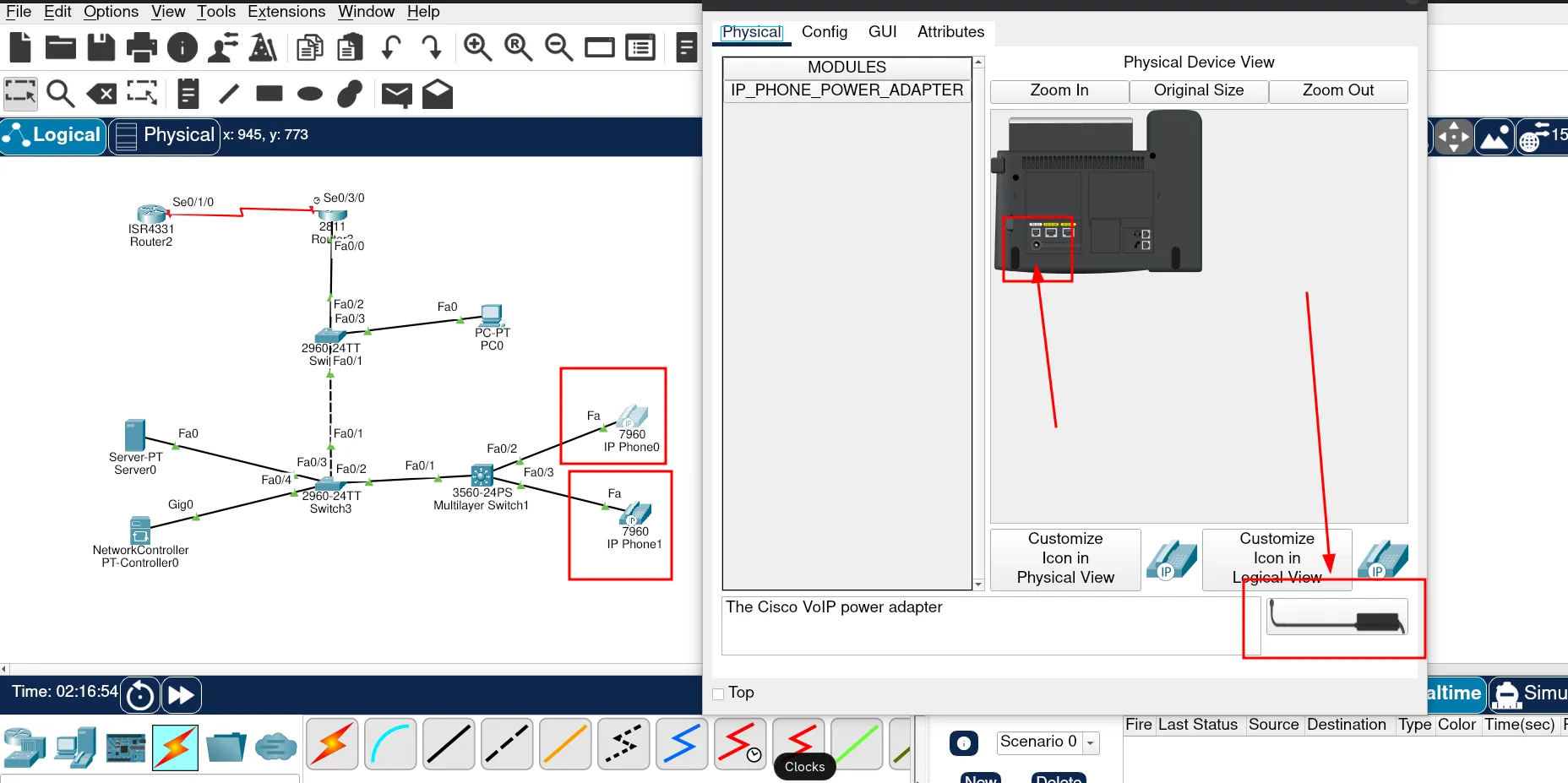
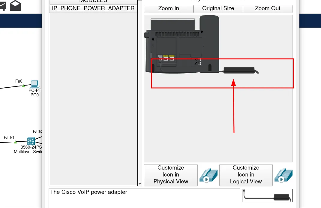
2960-24TT:A switch that allows devices inside a LAN (computers, printers, phones) to connect. It does not route traffic between networks. In this scenario, we will use two switches of this type. With a normal switch like the 2960-24TT, you need an Ethernet cable and a separate power adapte.

3560-24PS:This switch is a bit special because it supports PoE (Power over Ethernet), which means a single cable provides both power and network. This makes it perfect for configuring phones because no extra cables are needed — just one Ethernet cable sends both data and power.

IP Phone:A telephone that wosrks over a computer network instead of traditional phone lines. These IP phones will belong to VLAN 30.

PC:We will use PCs that belong to VLAN 10.

Server:A computer that provides services or resources. In this project, we will configure services such as web hosting or email.

Network Controller:This device helps manage routers and switches. For example, instead of checking the health status of each router directly, you can use a network controller to monitor and manage all devices centrally.

Adding Devices on Packet Tracer
Now that we know which devices we need to add in Packet Tracer, let’s start by locating the Network Devices.

Great! We’ve found the network devices. Next, let’s move on to the Switches.

Finally, we just need to add the End Devices. Let’s locate them as well.

Now that we have all the devices for the design, we can start connecting them. But first, here is the list of cables we will use.
Console cable:This cable is very common in networking environments because it allows you to connect to devices and configure them directly. It usually comes in different forms, such as serial console cables or USB console cables.

Straight-through copper and Crossover cables
-
Straight-through cables are used to connect different types of devices, such as:
- Computer → Switch
- Computer → Hub
- Router → Switch
-
Crossover cables were traditionally used to connect similar devices directly, such as:
- PC ↔ PC
- Switch ↔ Switch
- Router ↔ Router
These cables look the same on the outside; the difference lies in their internal wiring standard. (In modern hardware, Auto-MDIX automatically adjusts, so crossover cables are less necessary — but in Packet Tracer, the distinction still matters.)

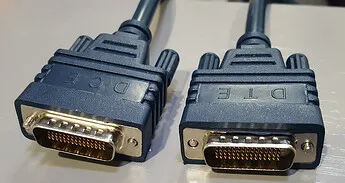
Serial DCE and DTE
- DCE (Data Communications Equipment): Usually ISP devices (like modems, CSU/DSU). These provide the clocking signal.
- DTE (Data Terminal Equipment): Customer routers that synchronize with the DCE.
Cable Types
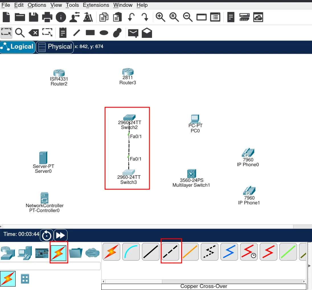
Perfect, now that we understand how these cables work, let’s connect the devices in Packet Tracer.
As you can see in the image below, we are using a crossover cable because we are connecting similar devices. The diagram also shows the interfaces used for this connections.
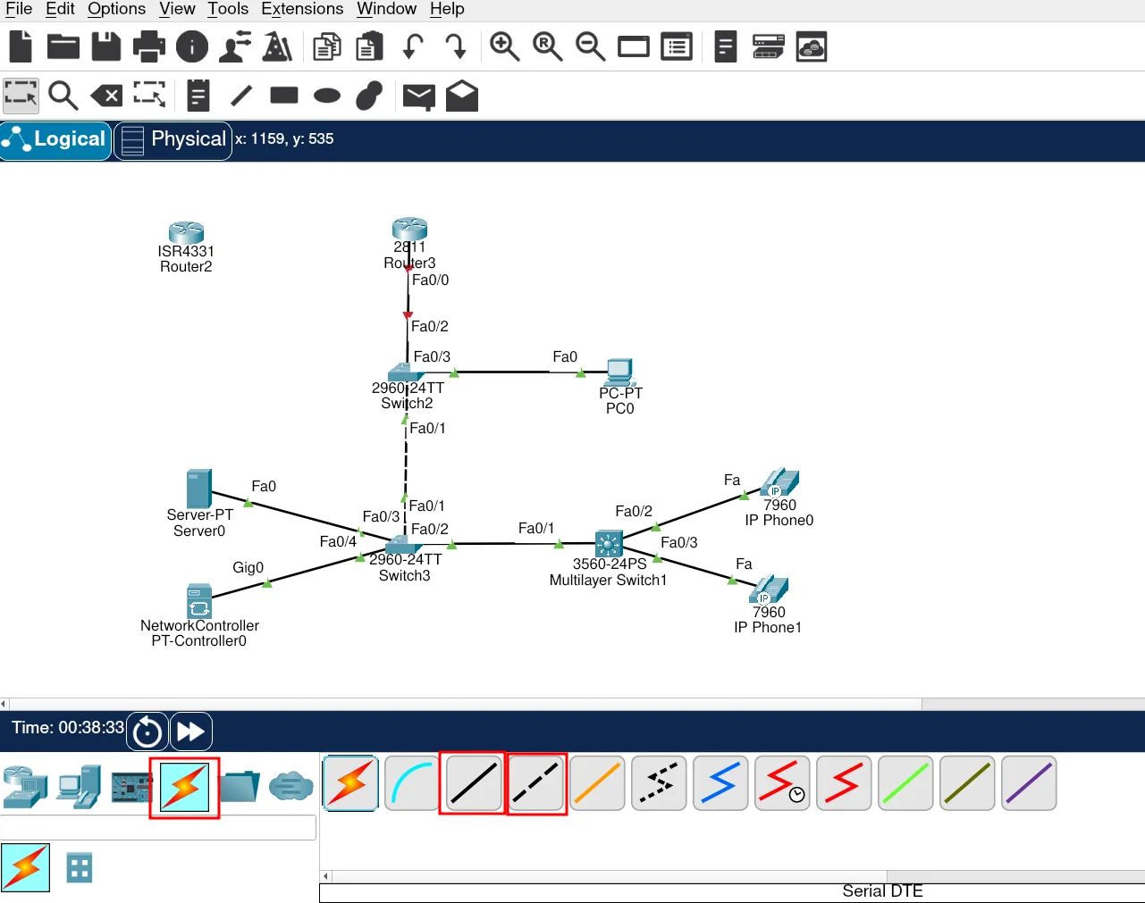
Now, let’s connect all the devices that require straight-through and crossover cables.
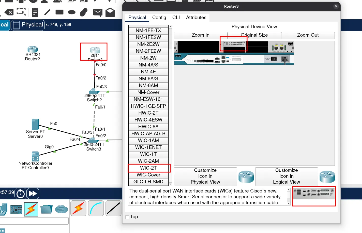
Next, we’ll connect the ISP router and the customer router. In Packet Tracer, routers do not always come with serial interfaces by default, so we need to add WIC-2T modules (or equivalent) before we can connect serial DTE/DCE cables.
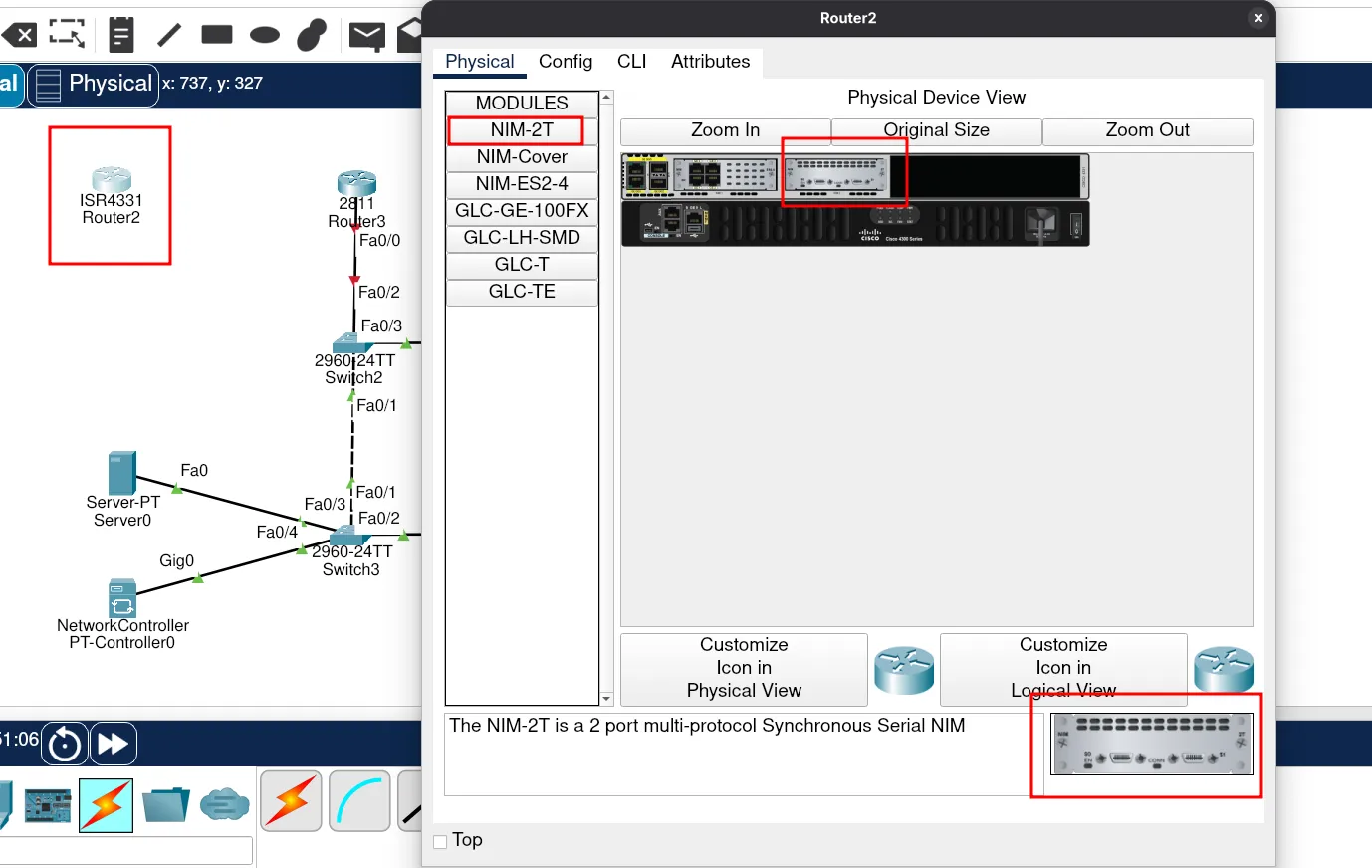
Do the same on the customer router to add serial interfaces.
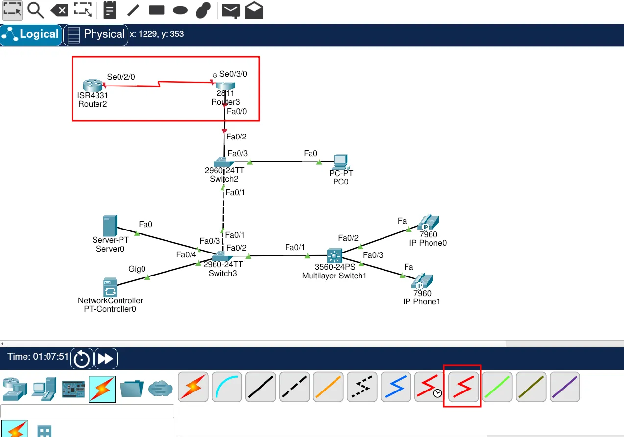
Now we can connect the ISP router with the customer router using the serial link.
Finally, all our devices are connected. We can now move on to the most exciting part: configuration — my favorite step!
Devices Configuration
Before we start configuring, it’s always helpful to keep a subnet mask reference table at hand. This table is a great resource because it shows the relationship between CIDR notation, subnet masks, and the number of usable hosts. In simple words, it tells you exactly how many devices can fit into each subnet.
| CIDR | Binary Mask | Subnet Mask | Usable Hosts ||------|--------------------------------------|--------------------|-----------------|| /8 | 11111111.00000000.00000000.00000000 | 255.0.0.0 | 16,777,214 || /9 | 11111111.10000000.00000000.00000000 | 255.128.0.0 | 8,388,606 || /10 | 11111111.11000000.00000000.00000000 | 255.192.0.0 | 4,194,302 || /11 | 11111111.11100000.00000000.00000000 | 255.224.0.0 | 2,097,150 || /12 | 11111111.11110000.00000000.00000000 | 255.240.0.0 | 1,048,574 || /13 | 11111111.11111000.00000000.00000000 | 255.248.0.0 | 524,286 || /14 | 11111111.11111100.00000000.00000000 | 255.252.0.0 | 262,142 || /15 | 11111111.11111110.00000000.00000000 | 255.254.0.0 | 131,070 || /16 | 11111111.11111111.00000000.00000000 | 255.255.0.0 | 65,534 || /17 | 11111111.11111111.10000000.00000000 | 255.255.128.0 | 32,766 || /18 | 11111111.11111111.11000000.00000000 | 255.255.192.0 | 16,382 || /19 | 11111111.11111111.11100000.00000000 | 255.255.224.0 | 8,190 || /20 | 11111111.11111111.11110000.00000000 | 255.255.240.0 | 4,094 || /21 | 11111111.11111111.11111000.00000000 | 255.255.248.0 | 2,046 || /22 | 11111111.11111111.11111100.00000000 | 255.255.252.0 | 1,022 || /23 | 11111111.11111111.11111110.00000000 | 255.255.254.0 | 510 || /24 | 11111111.11111111.11111111.00000000 | 255.255.255.0 | 254 || /25 | 11111111.11111111.11111111.10000000 | 255.255.255.128 | 126 || /26 | 11111111.11111111.11111111.11000000 | 255.255.255.192 | 62 || /27 | 11111111.11111111.11111111.11100000 | 255.255.255.224 | 30 || /28 | 11111111.11111111.11111111.11110000 | 255.255.255.240 | 14 || /29 | 11111111.11111111.11111111.11111000 | 255.255.255.248 | 6 || /30 | 11111111.11111111.11111111.11111100 | 255.255.255.252 | 2 || /31 | 11111111.11111111.11111111.11111110 | 255.255.255.254 | 0 (point-to-point) || /32 | 11111111.11111111.11111111.11111111 | 255.255.255.255 | 0 (1 host only) |Where to Start Configuration
I recommend always starting with the router. The router gives you the “big picture” of your network configuration. When I begin, I ask myself:
How many VLANs do I need?
Which VLANs will provide DHCP services?
How many phones do I need to configure?
Answering these questions first makes the rest of the configuration much easier.
Router Configuration (RTR-core)
!VLAN-10 - Users 192.168.10.0 (255.255.255.0)/24!VLAN-20 - Services 192.168.20.0 (255.255.255.0)/24!VLAN-30 - Voip 192.168.30.0 (255.255.255.0 )/24
!RTR-core
enable
conf terminal
hostname RTR-core
no ip domain-lookup
interf f0/0  no shutdown  exit
interf f0/0.10  description GWT: VLAN 10 Users  encaps dot1q 10  ip add 192.168.10.1 255.255.255.0  exit
interf f0/0.20  description GWT: VLAN 20 Services  encaps dot1q 20 native  ip add 192.168.20.1 255.255.255.0  exit
interf f0/0.30  description GWT: VLAN 30 Voip  encaps dot1q 30  ip add 192.168.30.1 255.255.255.0  exit
ip dhcp excluded-address 192.168.10.1 192.168.10.3ip dhcp pool VLAN10    network  192.168.10.0 255.255.255.0    dns-server 192.168.20.100    default-router 192.168.10.1    exit

ip dhcp excluded-address 192.168.30.1ip dhcp pool VLAN30    network 192.168.30.0 255.255.255.0    default-router 192.168.30.1    option 150 ip 192.168.30.1    exit
telephony-service    max-ephone 2    max-dn 2    ip source-address 192.168.30.1 port 2000    auto assign 1 to 2    exit
ephone-dn 1    number 11001    exit
ephone-dn 2    number 11002    exit
router ospf 1    network 192.168.10.0 0.0.0.255 area 0    network 192.168.20.0 0.0.0.255 area 0    network 192.168.30.0 0.0.0.255 area 0    passive-interf f0/0.10    passive-interf f0/0.20    passive-interf f0/0.30    exit
Now, let’s copuy paste this script into the router core
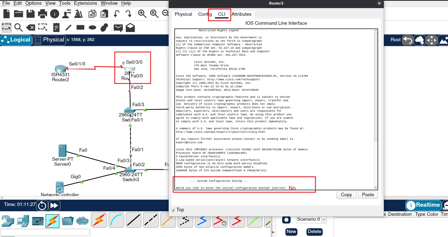
💡 Tip: If you make a mistake, you can reset the router with:
enable
erase startup-config
reload
Switch Configurations
Here’s how to configure each switch (distribution and VoIP).
Switch 1 – Distribution (SWT-DIST01)
!VLAN-10 - Users 192.168.10.0 (255.255.255.0)/24!VLAN-20 - Services 192.168.20.0 (255.255.255.0)/24!VLAN-30 - Voip 192.168.30.0 (255.255.255.0 )/24

!SWT-DIST01
enable
conf terminal
hostname SWT-DIST01
no ip domain-lookup
vlan 10    name Users    exit
vlan 20    name Services    exit
vlan 30    name Voip    exit

 interf range f0/1-2  switchport mode trunk  switchport trunk native vlan 20  switchport trunk allow vlan 10,30,20  exit
interf range f0/3-6  switchport mode access  switchport access vlan 10  exit

interf vlan 20    desc ip for remote Services    ip add 192.168.20.22 255.255.255.0    no shutdown    exit
banner motd #      .-"      "-.     /            \    |,  .-.  .-.  ,|    | )(_o/  \o_)( |    |/     /\     \|    (_     ^^     _)     \__|IIIIII|__/      | \IIIIII/ |      \          /       `--------`
!!!  Unauthorized Access is Forbidden !!!#
enable secret admin
line console 0logging synchronousexec-timeout 6password adminloginexit
username intern privilege 1 password adminusername admin privilege 15 secret admin
crypto key generate rsaip domain-name dspycode.comcrypto key generate rsa general-keys modulus 1024ip ssh version 2
line vty 0 4logging synchronousexec-timeout 5 30login localtransport input sshexit
service password-encryption
ip default-gateway 192.168.20.1
Switch 2 – Distribution (SWT-DIST02)
(Similar structure, adjusted for VLAN 20 access and IP address 192.168.20.23)
!VLAN-10 - Users 192.168.10.0 (255.255.255.0)/24!VLAN-20 - Services 192.168.20.0 (255.255.255.0)/24!VLAN-30 - Voip 192.168.30.0 (255.255.255.0 )/24

!SWT-DIST02
enable
conf terminal
hostname SWT-DIST02
no ip domain-lookup
vlan 10    name Users    exit
vlan 20    name Services    exit
vlan 30    name Voip    exit

 interf range f0/1-2  switchport mode trunk  switchport trunk native vlan 20  switchport trunk allow vlan 10,30,20  exit
interf range f0/3-4  switchport mode access  switchport access vlan 20  exit

interf vlan 20    desc ip for remote Services    ip add 192.168.20.23 255.255.255.0    no shutdown    exit
banner motd #      .-"      "-.     /            \    |,  .-.  .-.  ,|    | )(_o/  \o_)( |    |/     /\     \|    (_     ^^     _)     \__|IIIIII|__/      | \IIIIII/ |      \          /       `--------`
!!!  Unauthorized Access is Forbidden !!!#
enable secret admin
line console 0logging synchronousexec-timeout 6password adminloginexit
username intern privilege 1 password adminusername admin privilege 15 secret admin
crypto key generate rsaip domain-name dspycode.comcrypto key generate rsa general-keys modulus 1024ip ssh version 2
line vty 0 4logging synchronousexec-timeout 5 30login localtransport input sshexit
service password-encryption
ip default-gateway 192.168.20.1
Switch 3 – VoIP (SWT-VOIP)
(Configured for voice VLAN 30, with IP 192.168.20.24)
!VLAN-10 - Users 192.168.10.0 (255.255.255.0)/24!VLAN-20 - Services 192.168.20.0 (255.255.255.0)/24!VLAN-30 - Voip 192.168.30.0 (255.255.255.0 )/24
!SWT-VOIP
enable
conf terminal
hostname SWT-VOIP
no ip domain-lookup
vlan 10    name Users    exit
vlan 20    name Services    exit
vlan 30    name Voip    exit
interf f0/1  switchport mode trunk  switchport trunk native vlan 20  switchport trunk allow vlan 10,30,20  exit
interf range f0/2-3  switchport mode access  switchport voice vlan 30    no shutdown  exit
interf vlan 20    desc ip for remote Services    ip add 192.168.20.250 255.255.255.0    no shutdown    exit

banner motd #      .-"      "-.     /            \    |,  .-.  .-.  ,|    | )(_o/  \o_)( |    |/     /\     \|    (_     ^^     _)     \__|IIIIII|__/      | \IIIIII/ |      \          /       `--------`
!!!  Unauthorized Access is Forbidden !!!#
enable secret admin
line console 0logging synchronousexec-timeout 6password adminloginexit
username intern privilege 1 password adminusername admin privilege 15 secret admin
crypto key generate rsaip domain-name dspycode.comcrypto key generate rsa general-keys modulus 1024ip ssh version 2
line vty 0 4logging synchronousexec-timeout 5 30login localtransport input sshexit
service password-encryption
ip default-gateway 192.168.20.1
SSH into the switch
On the PC’s desktop → open the Command Prompt:
ssh -l admin 192.168.1.2Now, let’s power on the phones and check if they are working.
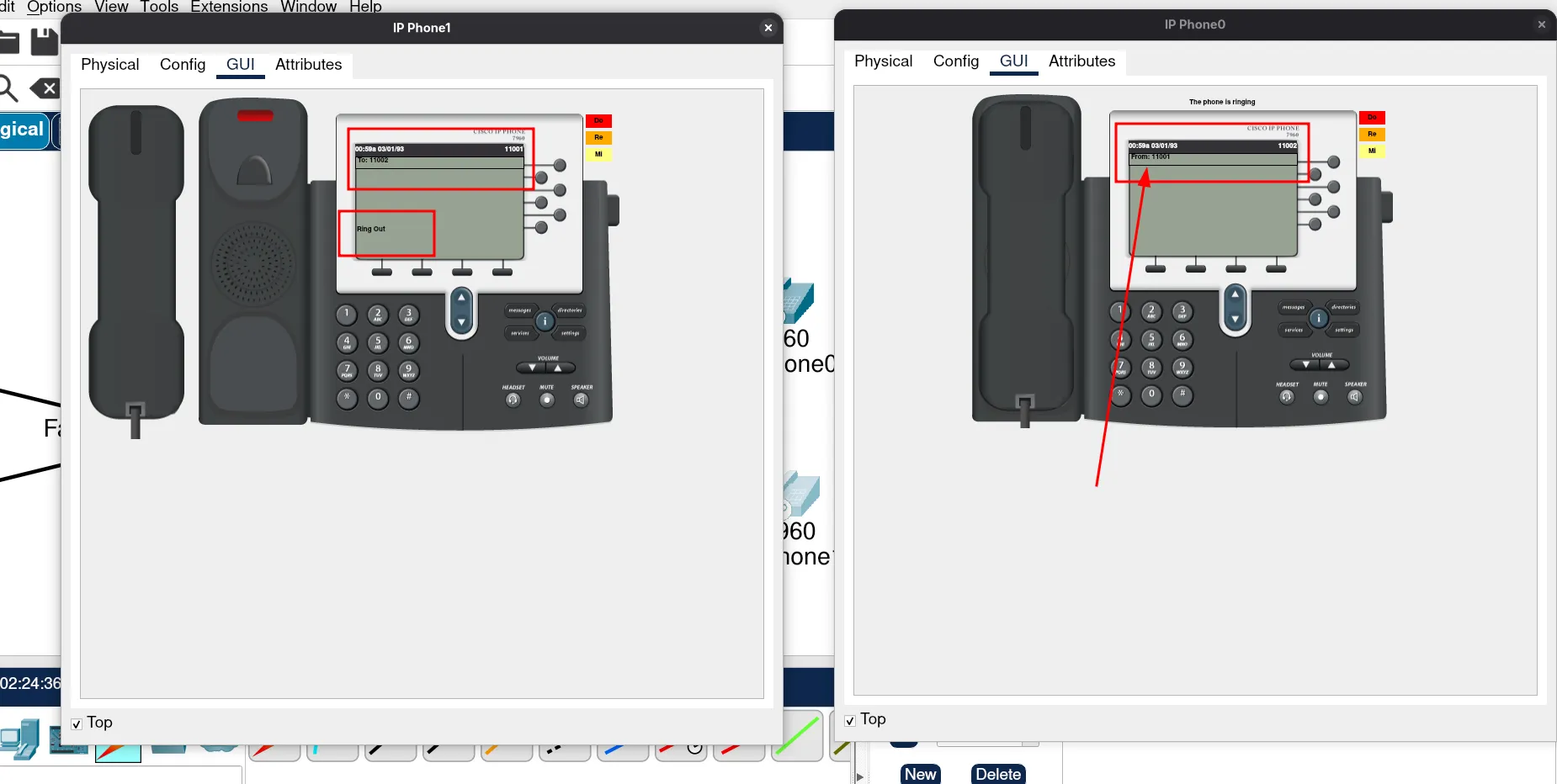
They should look something like this:
Perfect! Let’s test if our phones are working. To do this, look at the top part of the phone’s display. You should see a number there — it must match the number you configured on the router.
To test calling, simply dial the number of the other phone.
Testing the DHCP Pool for VLAN 10
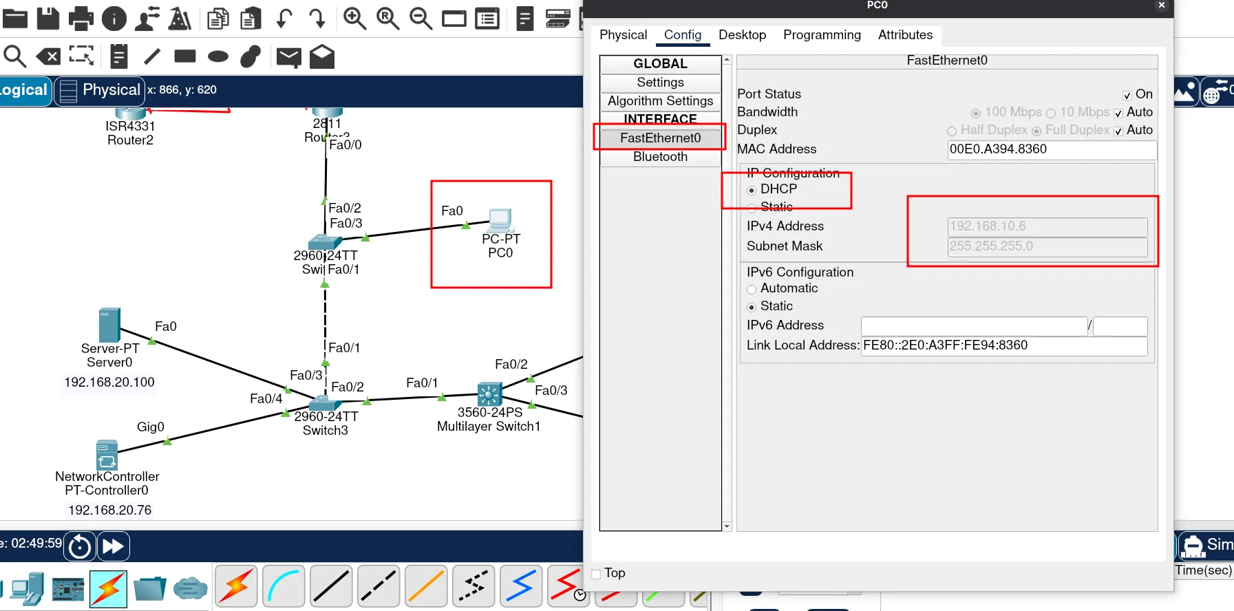
Next, let’s check the DHCP pool of VLAN 10. To test this configuration, open the user’s computer, configure it to use DHCP, and verify the settings.
If the computer receives an IP address, it means the DHCP server is working correctly.
Configuring the DNS Server
Now, let’s configure our DNS server. First, assign it an IP address from the VLAN Services network. In my case, I’ll use:
192.168.20.100
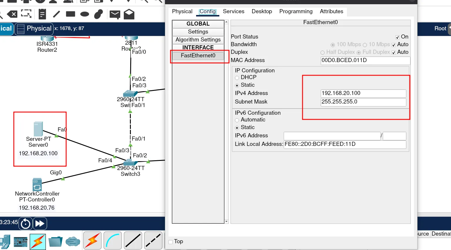
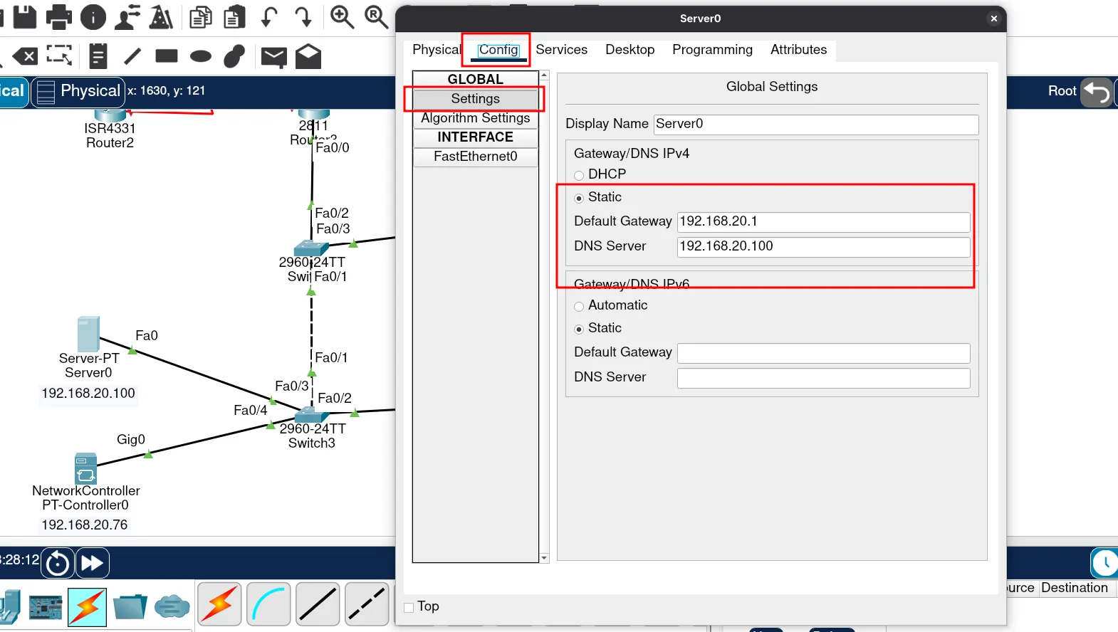
Next, we need to set the gateway IP for our DNS server. Remember, we already configured this on the router. If you check the router’s configuration script, you’ll see that the gateway IP is assigned to the VLAN Servicnpm es network.
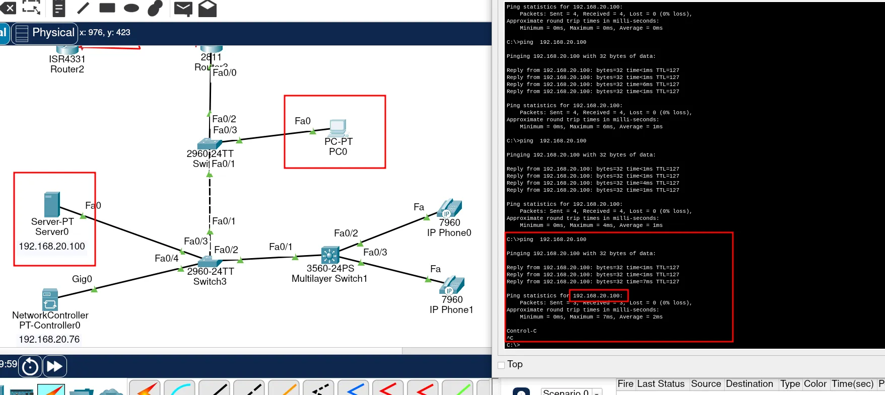
Testing Connectivity to the DNS Server
Now, let’s check if we can reach the DNS server from the VLAN Clients network. To do this, ping the server’s IP address: 192.168.20.100.
This DNS server will also act as our web server, so we will configure both DNS and web services on the same machine.
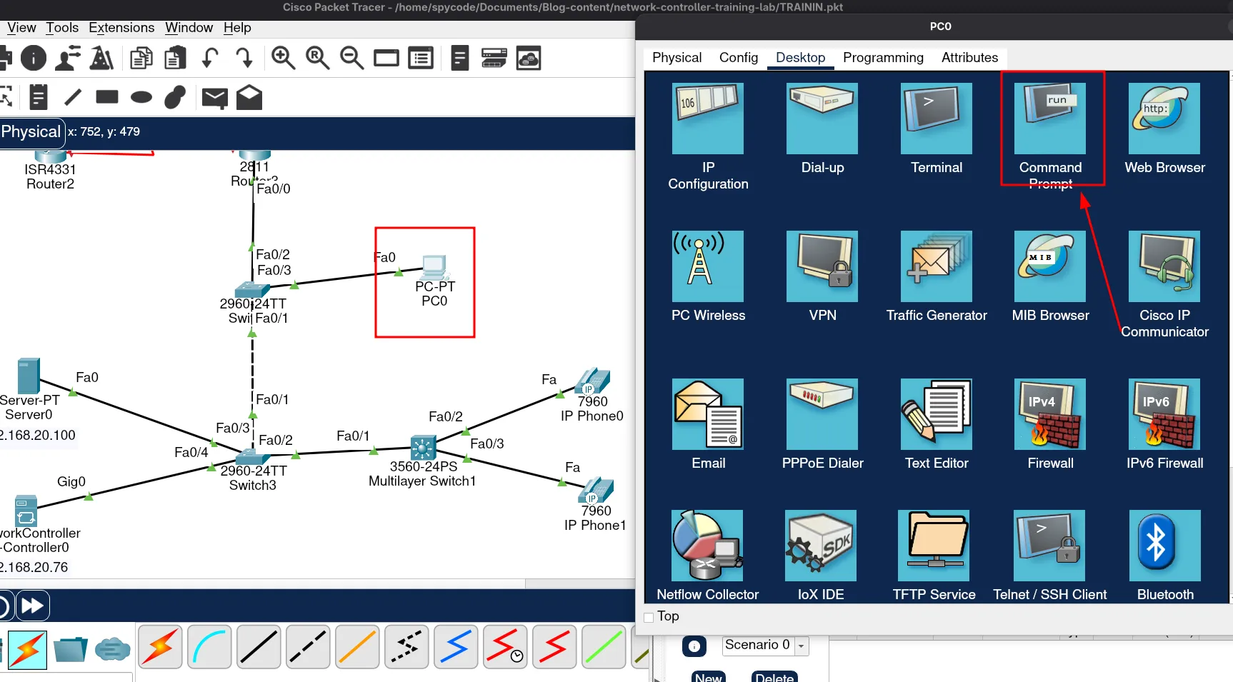
Run the following command in the terminal:
ping 192.168.20.100If you receive replies, then the DNS server is reachable.
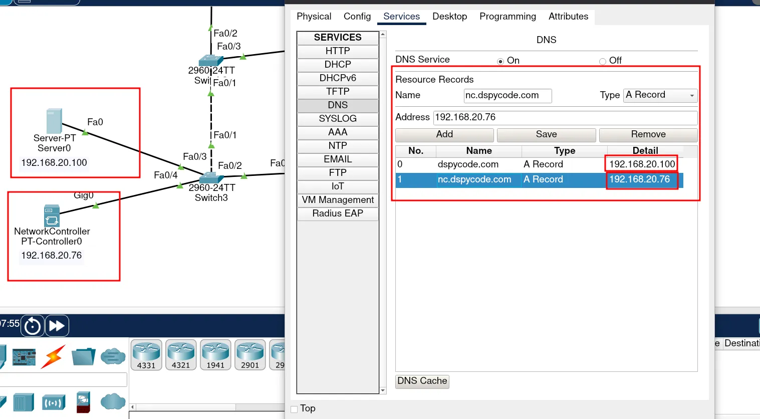
Now, we can proceed with configuring our DNS server. To do this, we need to define the DNS records that will point to our web server and our network controller.
In this case, I created two DNS entries:
One for the web server
One for the network controller
As you can see, we are using the same machine for the web server. Later, we will also configure the web server on this same server.
Awesome. Let’s proceed with configuring our web server.
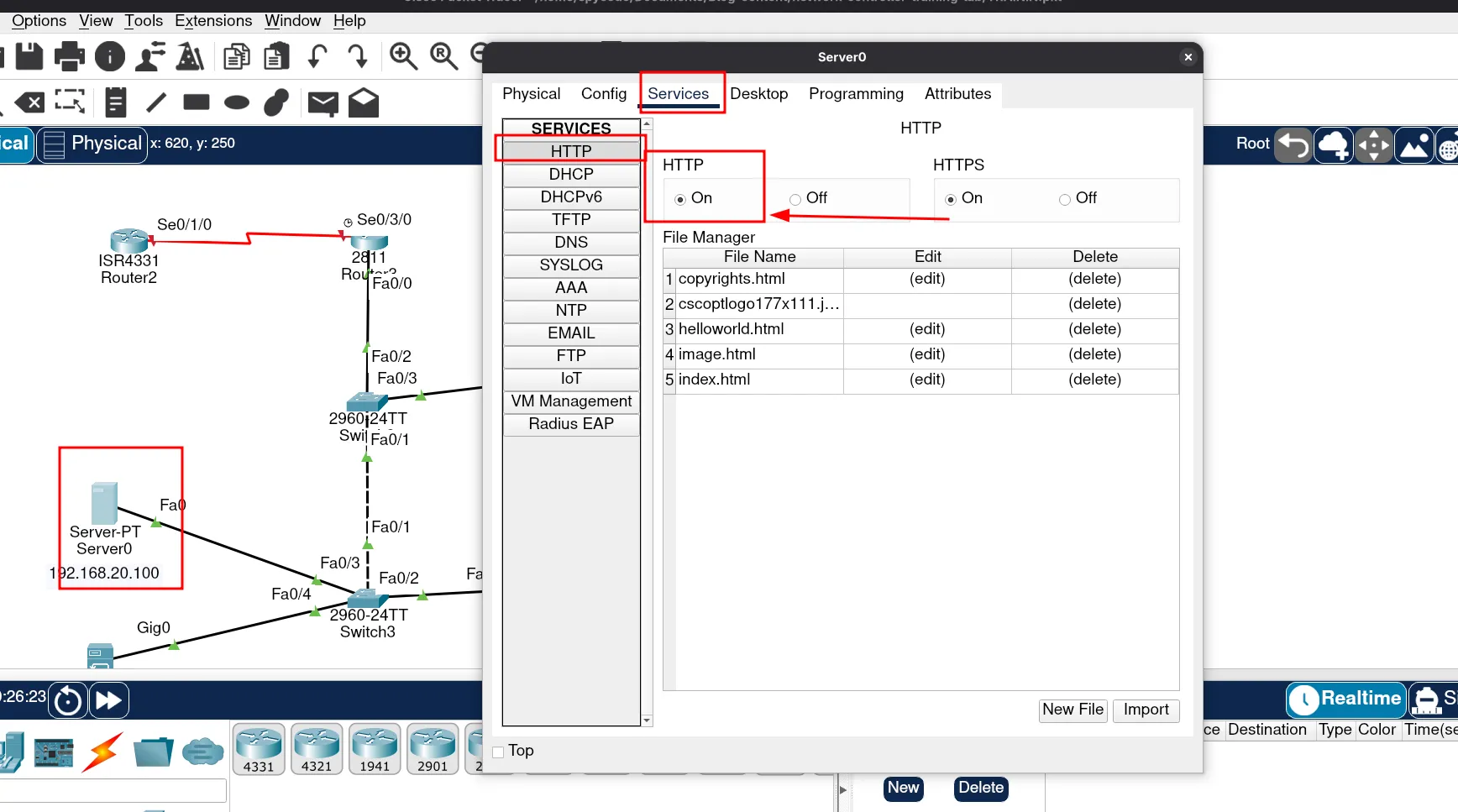
Now, let’s check if our web server is running. To do that, open a web browser and enter the DNS name of the web server.
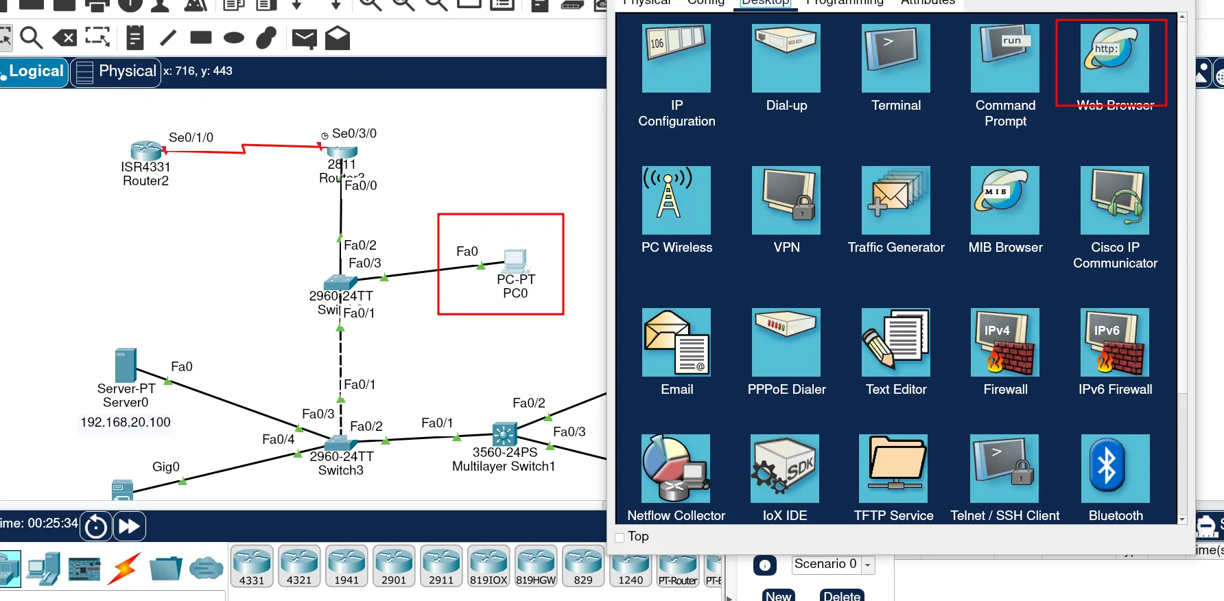
You should see something like this:
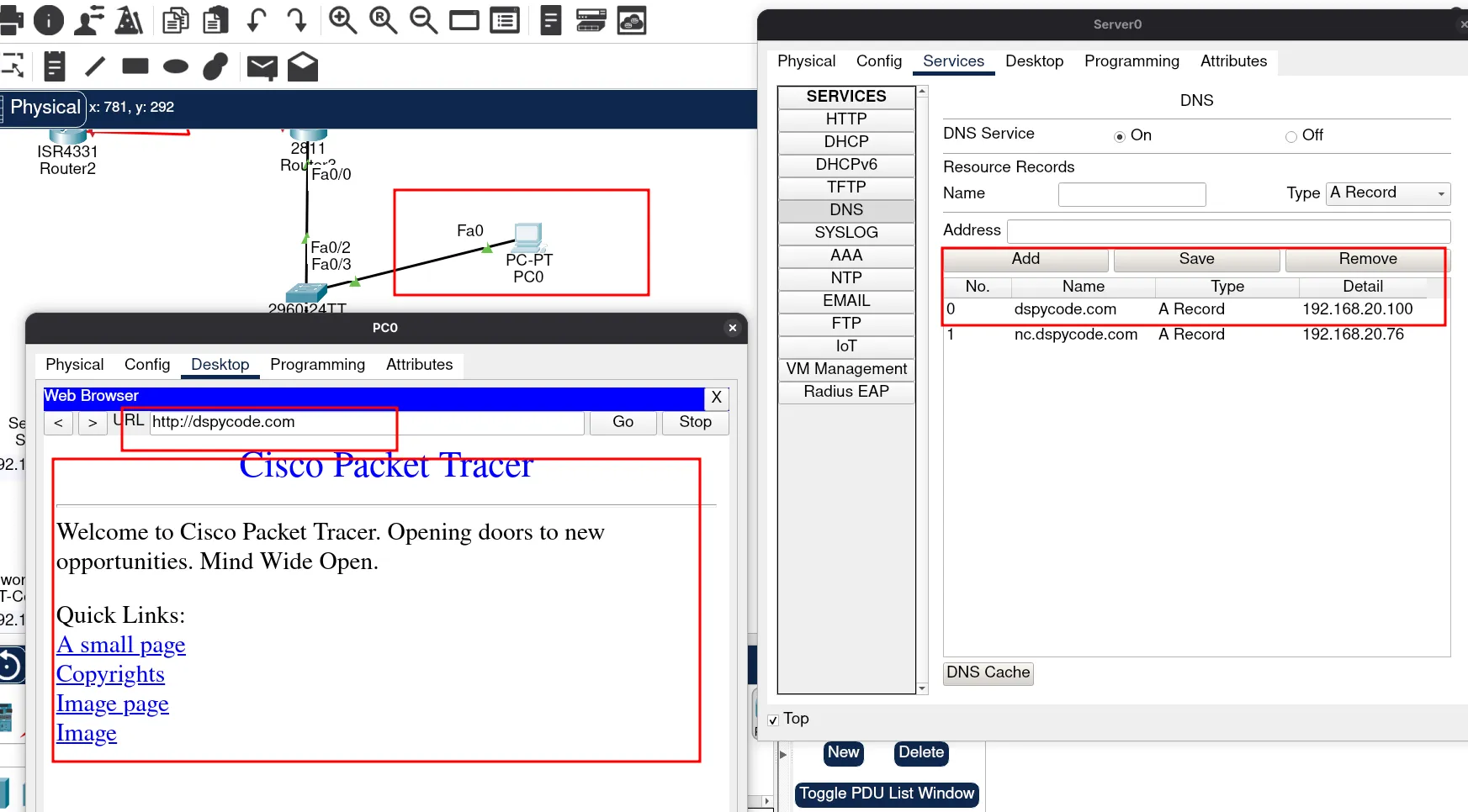
Awesome! We have completed our web server configuration. Now we can proceed with our network controller.
Network controller configuration
Ok, let’s start from scratch. The basic idea of having a network controller in your network is mainly for management. Think about how hard it would be to manage all these devices if you had three hundred devices in your company. It would be very hard to go to each switch individually to check the health of these devices. This is where the network controller comes into place.
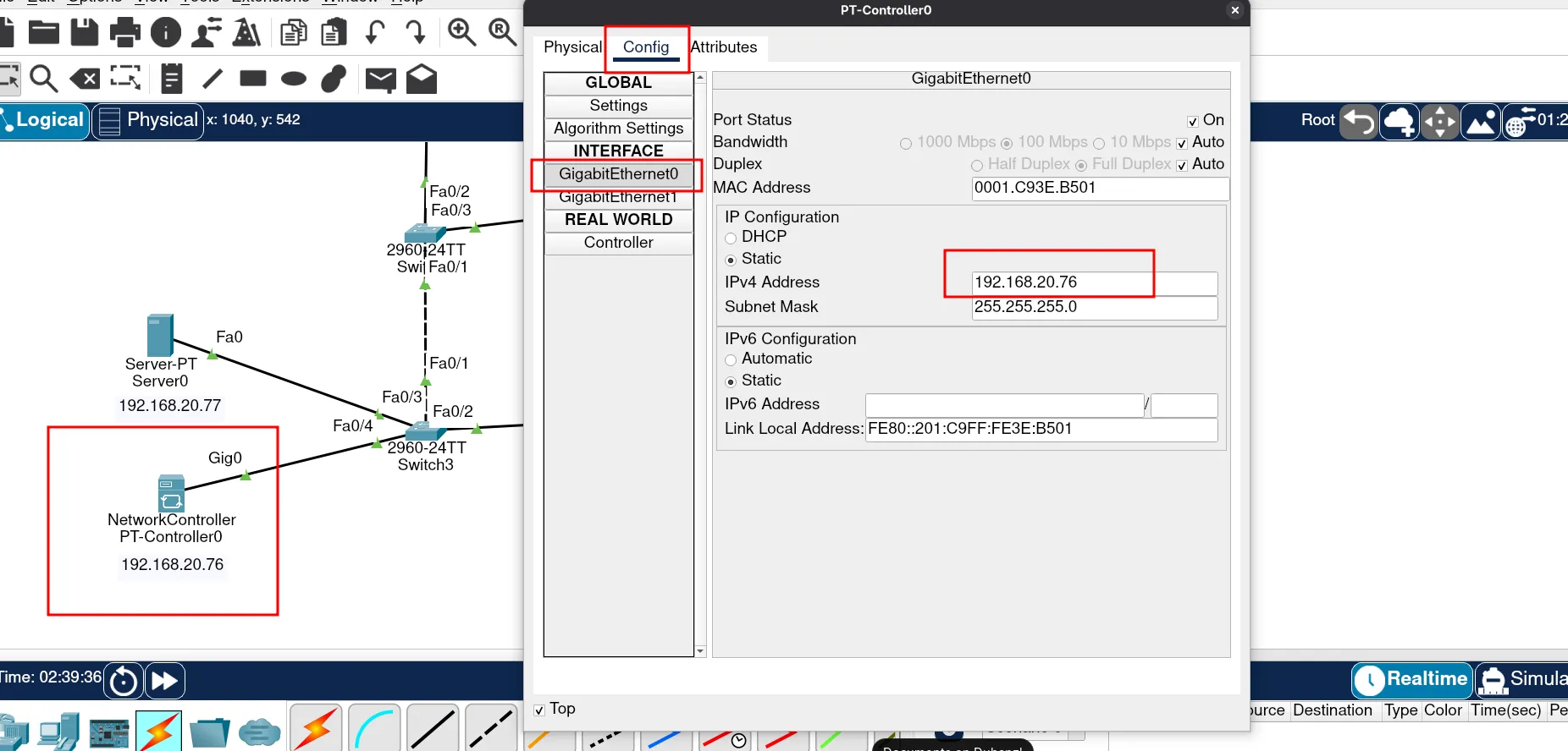
To start configuring a network controller, we need to assign an IP address and a gateway IP. This enables our network controller to reach out to other devices.
Let’s assign an IP address to our network controller.
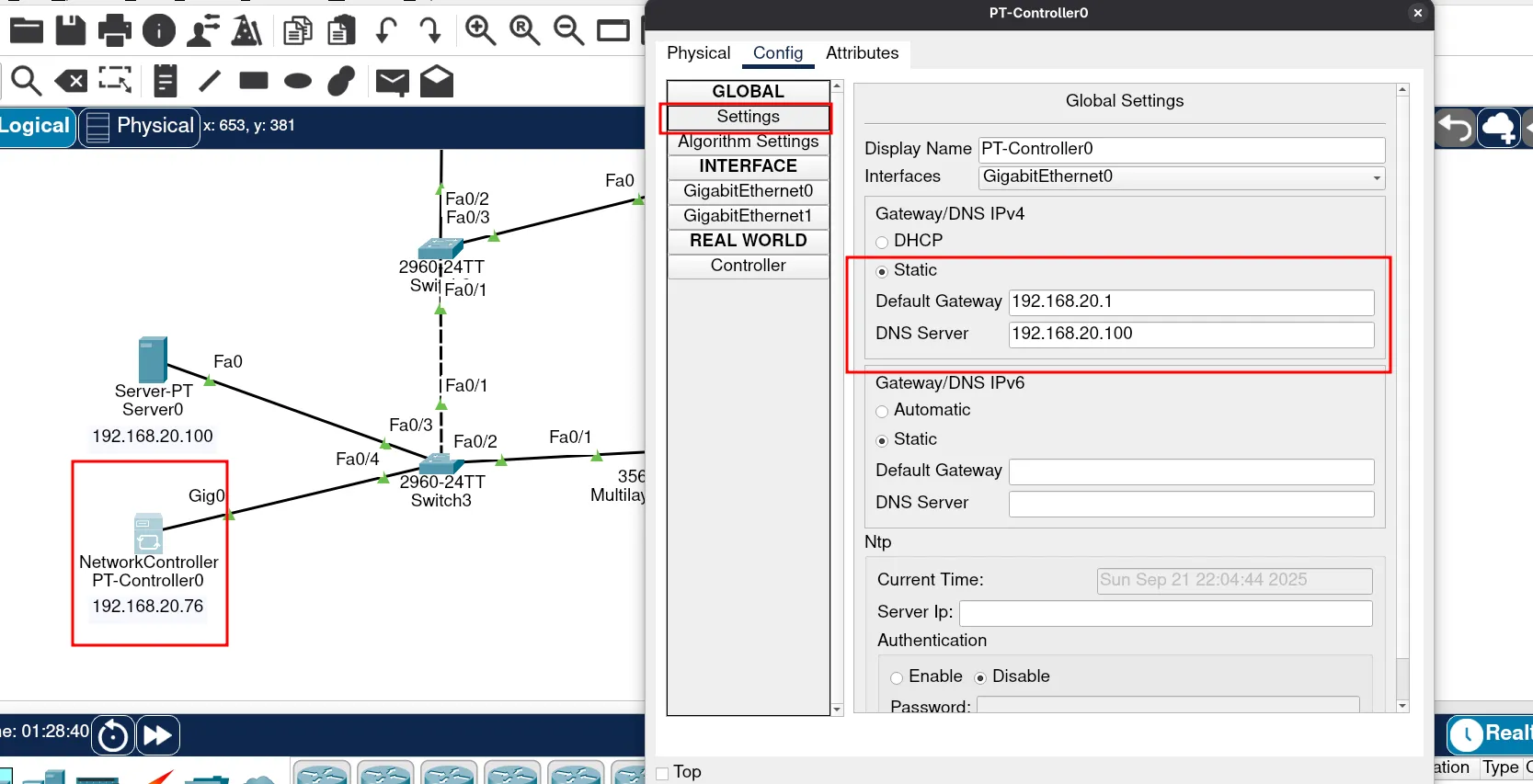
Finally, we can assign the gateway IP address to our network controller. Remember, we have already configured this. In this case, it will be the first usable IP address in the VLAN Services network.
Let’s log in to the network controller. To do this, open a browser and enter the DNS name of the network controller.
You should see something like this:
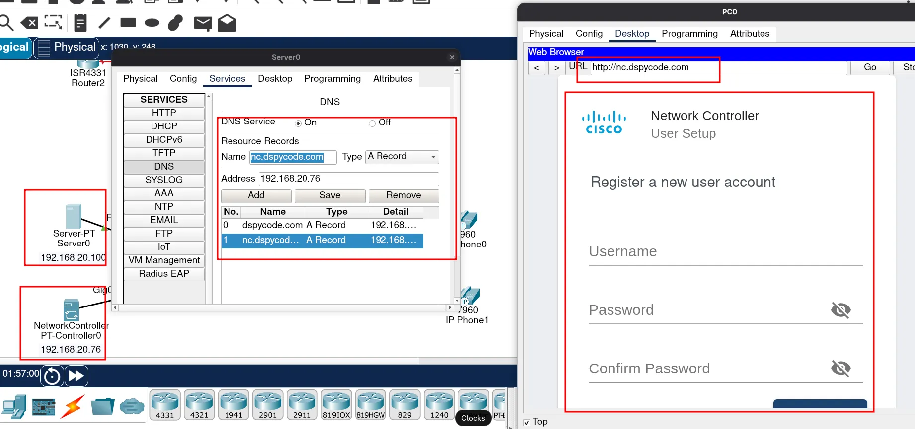
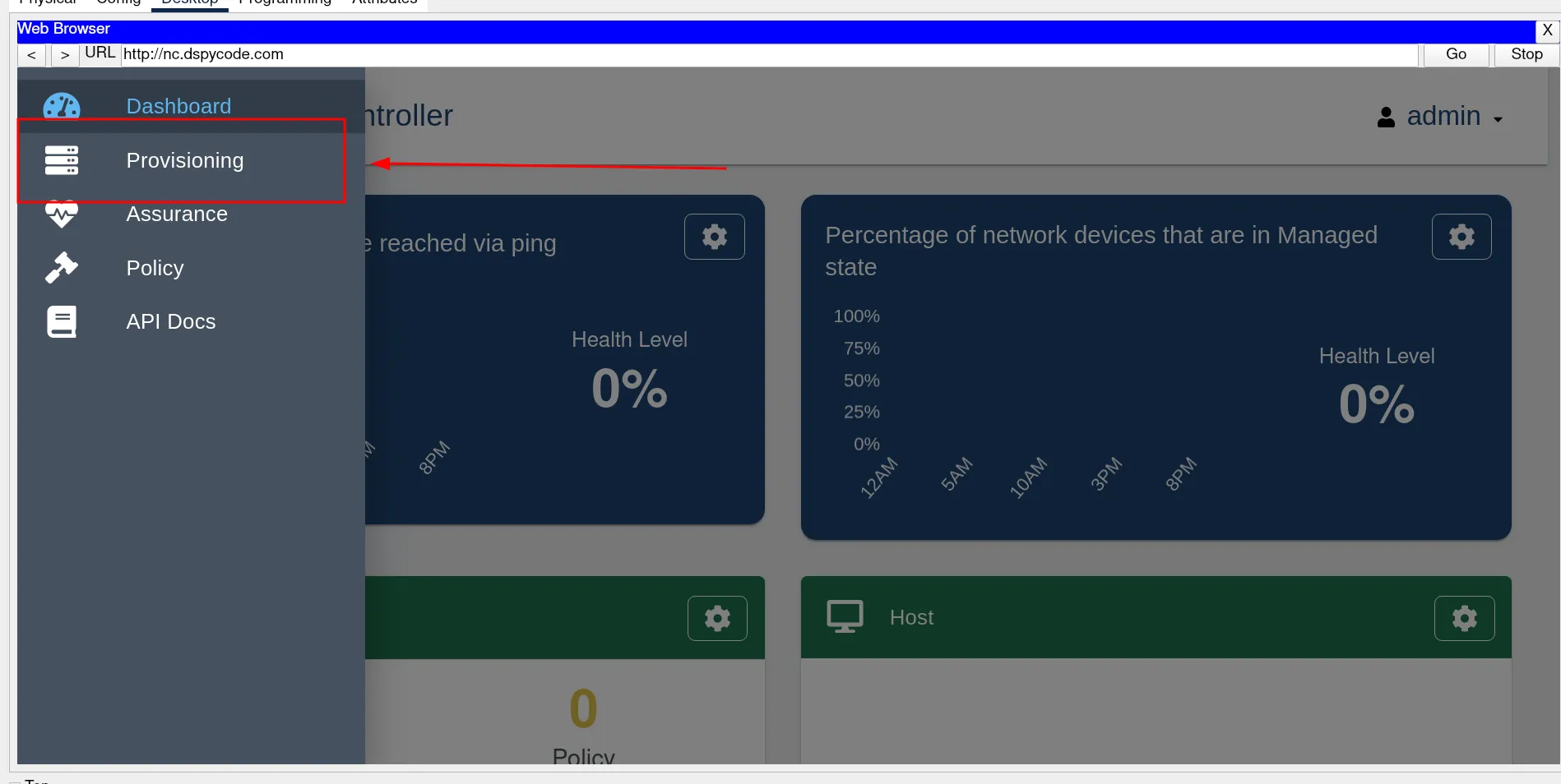
Let’s create a username and password. In my case, I just left it as “admin” for both.
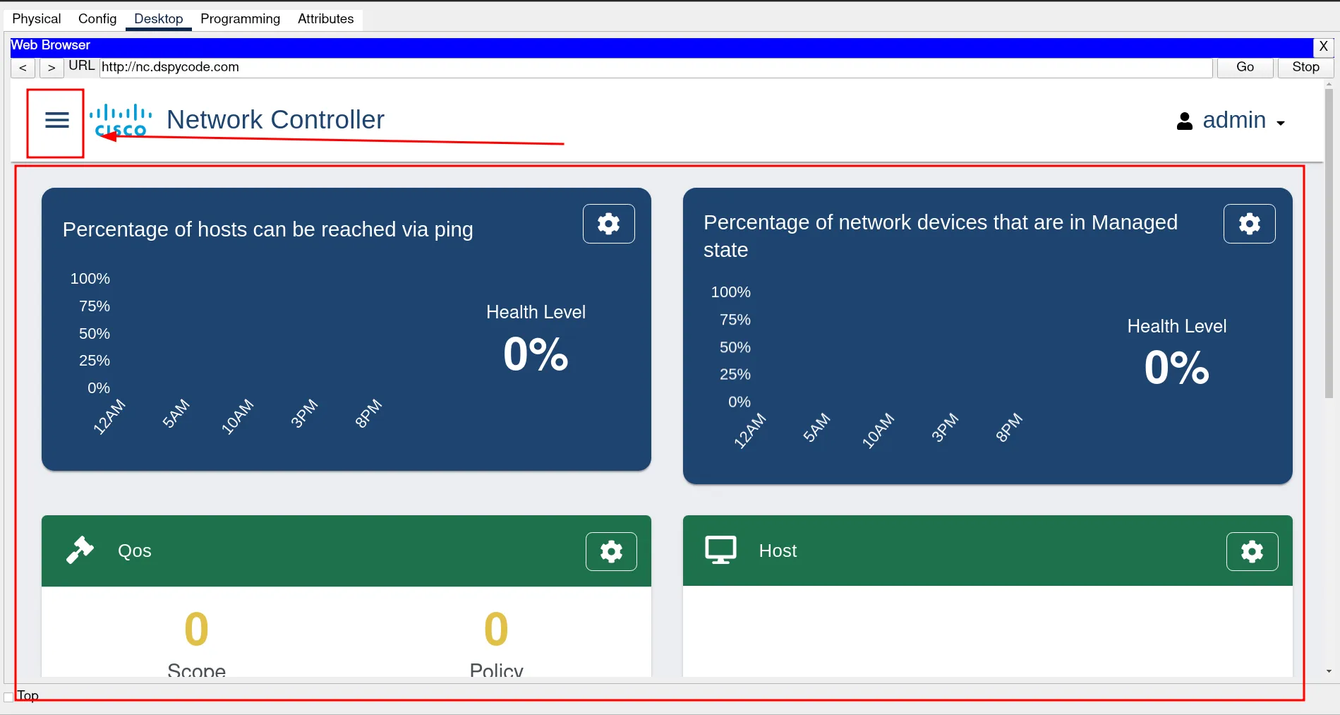
First stage click in the top corner Menu Icon and go to provisioning.
Second stage go to credentials
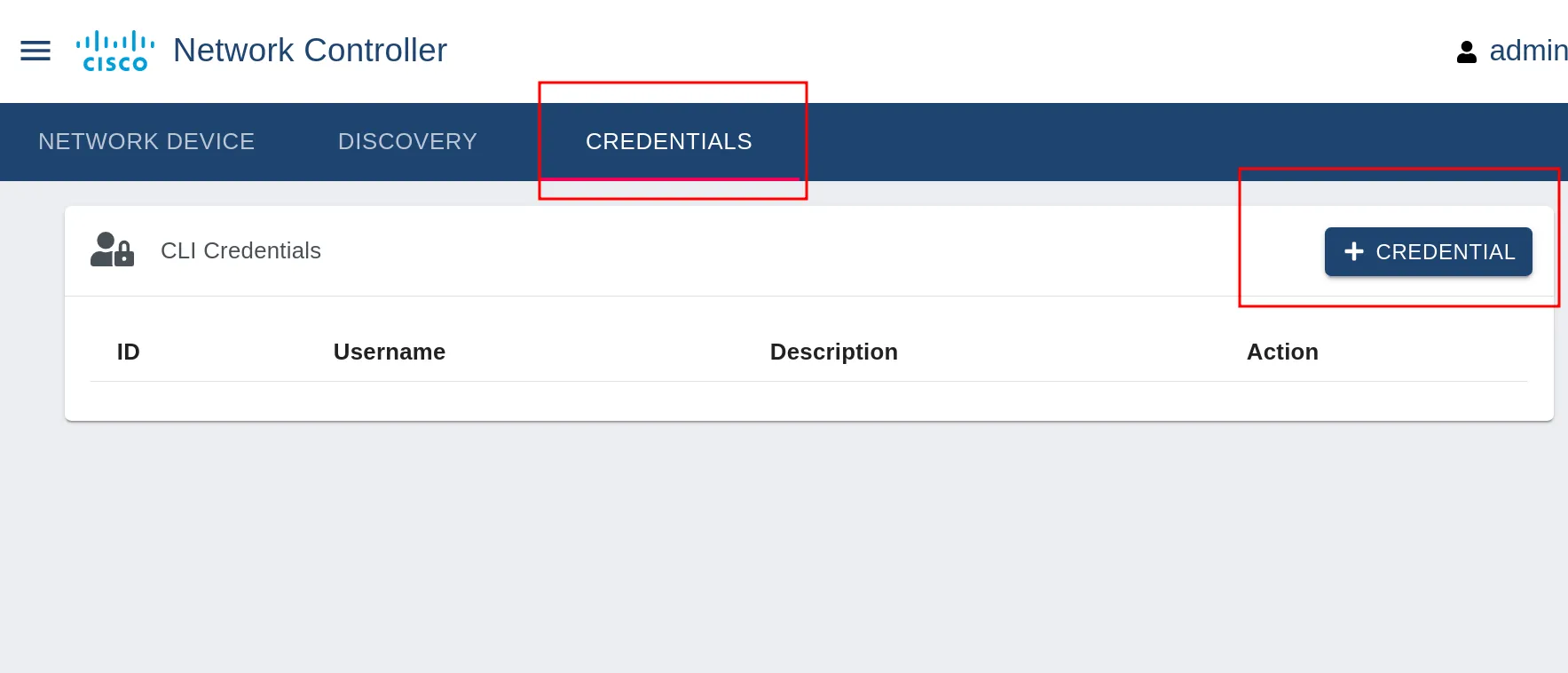
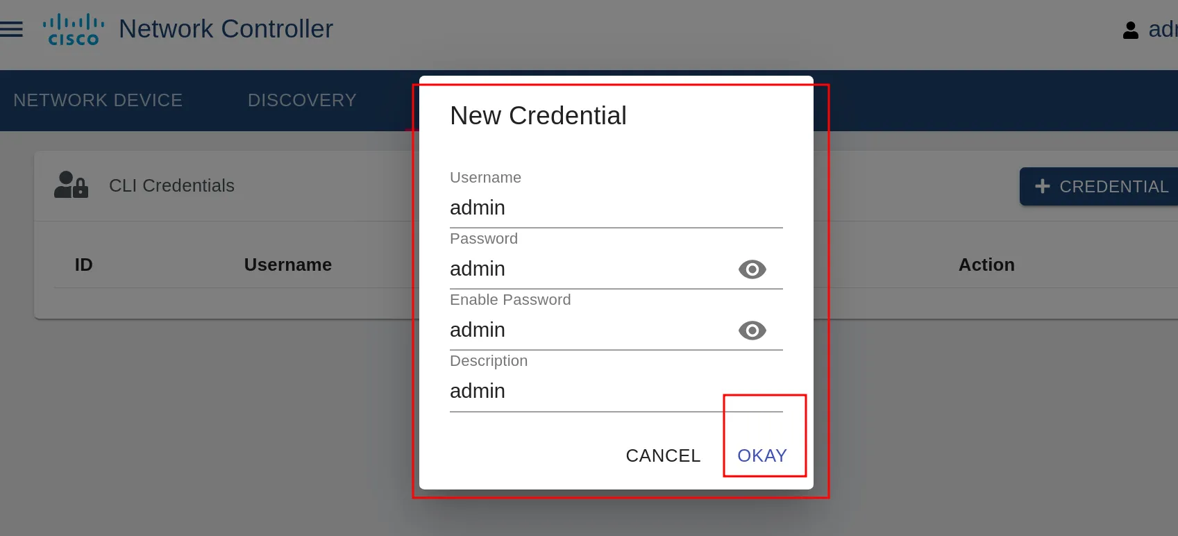
Third stage type the credentials.
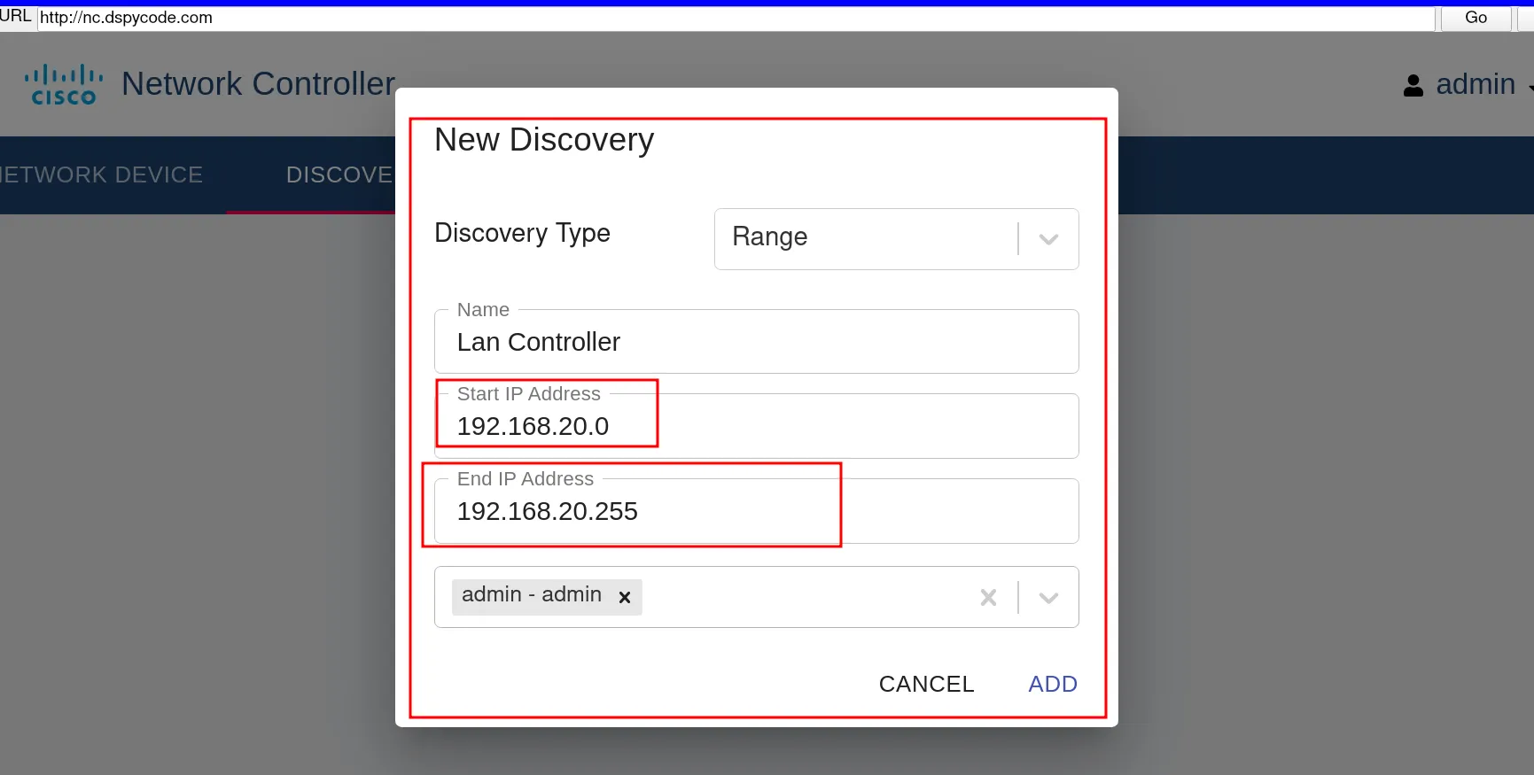
fourth stage go to discovery
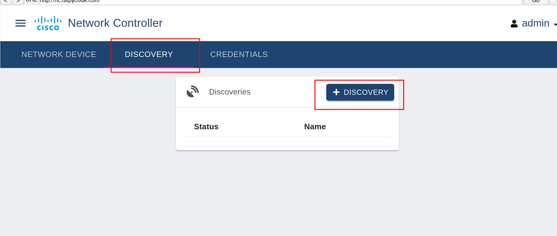
This stage is very important, so pay attention. In this step, we have to set the IP range of our network. Basically, the network controller will identify all the devices in the network. We could do this process one by one, but setting the range is the fastest way.